


For broader selection context, see Guide to Choosing Seal-less Magnetic Drive Pumps.
PCB developer pump gas binding happens when air, foam, CO2, or other non-condensable gas enters the pump suction or remains trapped in the pump and filter loop. The immediate result is no flow, low flow, unstable spray pressure, abnormal vibration, or a pump that looks like it is running dry even though liquid is still in the tank. The practical fix is to remove the trapped gas, stop new air from entering, protect the pump from dry-running damage, and adjust the suction layout, venting, liquid level, and PCB wet process filtration flow so the line stays flooded.
For PCB factories, this is not only a pump problem. A short period of unstable developer, etching, micro-etch, cleaning, or filtration circulation can leave residual dry film, uneven line width, pinholes, residual copper, poor hole metallization, or particle defects. OEM line builders and plant maintenance teams therefore need to treat gas binding as a process-risk item, not just as a routine pump restart issue.
What Gas Binding Looks Like on a PCB Line
Gas binding is different from a normal clogged filter or worn impeller, although the symptoms can overlap. The pump motor may run, but the pump casing contains too much gas for the impeller to build stable head. In a magnetic drive pump, the internal bearings and thrust surfaces still depend on liquid for lubrication and cooling, so repeated gas-bound starts can create heat damage similar to dry running.
| Field symptom | Likely process meaning | Immediate risk |
|---|---|---|
| Discharge pressure jumps up and down | Air or process gas is passing through the pump and filter loop intermittently | Unstable spray pressure, uneven developing or etching |
| Flow drops to near zero after restart | Pump casing, suction high point, or filter housing is not fully vented | Line stoppage and possible dry-running damage |
| Rattling, gravel-like noise, or vibration | Cavitation, vortex air, or gas pockets are reaching the impeller | Bearing wear, impeller erosion, particles in the wet process |
| Filter pressure rises but board quality does not improve | Filter may be gas locked, bypassing, or short-circuiting internally | Particles continue to return to the process tank |
| Developer or cleaning section foams heavily | Surfactants, agitation, free-fall return flow, or CO2 release is increasing entrained gas | Pump air binding and inconsistent spray coverage |
A useful diagnostic clue is timing. If the problem appears right after startup, filter replacement, tank refill, chemical make-up, or a low-level event, trapped air and poor venting should be checked first. If it appears gradually during production, look for foam generation, filter pressure rise, suction strainer blockage, crystallization, or a falling liquid level.
Why Developer and Etching Pumps Lose Flow
In PCB wet processing, gas can enter the pump loop from several directions. The QEEHUA local application notes point to developer solution crystallization, excessive foam, air pockets in upward suction piping, low liquid level, filter gas blockage, and improper vent location as recurring causes in PCB and electroplating systems.
1. Low level, vortexing, and insufficient submergence
When the tank outlet or pump suction is too close to the liquid surface, a vortex can draw air into the suction line. The problem may be visible as a whirlpool, but it can also be hidden under foam or inside a covered tank. PCB horizontal equipment with shallow tanks is especially sensitive because spray demand can change quickly while the tank level is still recovering.
QEEHUA source guidance for wet process systems recommends enough liquid coverage over the suction area, anti-vortex shielding at the draw-off point, and low-level interlock protection. For vertical submerged pumps, the submerged section must remain below the safe liquid level. For suction-lift systems, keep actual suction lift well below the pump rating and avoid expecting a self-priming pump to overcome poor suction geometry.
2. Suction piping that traps air
A suction pipe that climbs upward before entering the pump creates a high point where air accumulates. Direct reducers, undersized suction pipe, too many elbows, loose flanges, and worn gaskets can also create suction-side air problems. Because suction piping can operate below atmospheric pressure, a joint may pull air inward without visibly leaking liquid outward.

3. Developer chemistry that releases gas or foam
PCB developer lines often use alkaline carbonate chemistry. In DES lines and related developer sections, reaction byproducts and CO2 release can accumulate when venting and circulation are poor. Foam from surfactants or cleaning chemistry can also be pulled into the pump suction. Once foam reaches the impeller, the pump is moving a two-phase mixture instead of liquid, so head and flow collapse.
4. Filter housings that are not fully vented
Precision chemical filters can hold a large air pocket after cartridge replacement or chemical refill. If the air vent or pressure gauge is installed at a low point, the top of the filter housing remains gas-filled. The system then shows pressure instability, poor filtration, and flow loss even though the pump itself may be mechanically sound.
5. Crystallization, sludge, or particles around the suction
Developer crystallization, micro-etch residues, anode mud, copper particles, or filter debris can partially block the inlet. This lowers suction pressure and makes gas release more likely at the impeller eye. For magnetic drive pumps, solids are also a separate concern because magnetic pump clearances are tight and magnetic particles can damage internal rotating parts. If the liquid contains significant solids, add suitable filtration before the pump or consider a pump type designed for that duty.
Troubleshooting Sequence for Maintenance Teams
Start with the suction side and the venting path before replacing pump parts. Many gas-binding cases are caused by installation, level control, or filter operation, and replacing the pump will not solve the root cause if new gas continues to enter the loop.
| Step | What to check | Corrective action |
|---|---|---|
| 1. Make the pump safe | Power, chemical pressure, residual liquid, and drain status | Lock out power, depressurize, drain safely, and use chemical PPE before opening the system |
| 2. Flood and vent | Pump casing, suction line, filter top, and high points | Fill the casing, open the highest vent until no bubbles appear, then restart gradually |
| 3. Check suction level | Tank level above outlet, vortex marks, foam layer, and draw-off position | Raise minimum level, add an anti-vortex plate, or move the draw-off below the foam layer |
| 4. Inspect suction piping | Pipe diameter, reducers, high points, elbows, valves, and gasket condition | Use suction pipe at least equal to pump inlet size, remove upward pockets, and repair air leaks |
| 5. Compare flow and pressure | Actual flow, filter pressure, cartridge differential pressure, and spray header pressure | Clean or replace blocked filters, avoid overdriving cartridges, and match pump flow to filter capacity |
| 6. Review chemistry | Foam, temperature, crystallization, carbonate developer condition, and suspended solids | Control temperature, use proper defoaming practice, drain stagnant pump cavities, and clean crystallized deposits |
Do not keep restarting a gas-bound magnetic drive pump. A short no-flow period can remove the liquid film that cools and lubricates internal components. If the motor current drops abnormally, if flow disappears, or if the pump body becomes hot, stop the pump and find the suction or venting cause before restarting.
Pump and Filter Specification Checks
Gas binding is often designed into the line unintentionally. During new equipment design or retrofit review, check the pump, filter, tank, and piping as one hydraulic system.
| Specification item | Practical target for PCB wet process lines | Why it matters |
|---|---|---|
| Suction pipe size | Do not make the suction pipe smaller than the pump inlet; avoid sudden throat reductions | Lower suction velocity reduces vortexing, air release, and pump starvation |
| Suction pipe slope | Avoid upward pockets; slope the line so air can return to the tank or reach a proper vent | High points collect gas and create delayed no-flow events after restart |
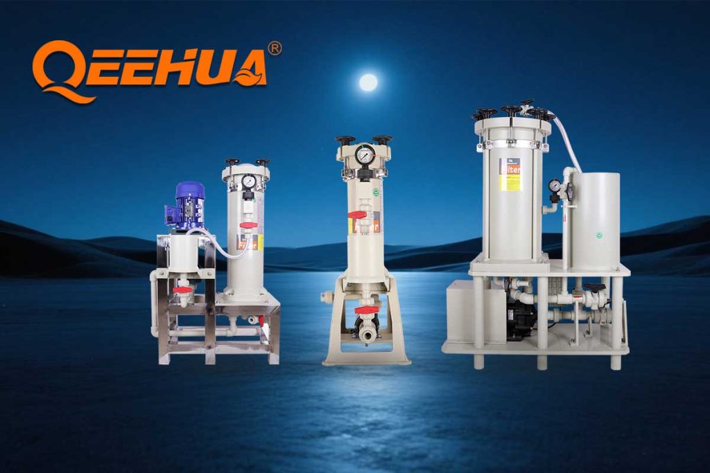
| Filter venting | Install the vent and pressure gauge at the highest practical point of the filter housing | Gas must leave the filter before stable filtration and pressure readings are possible |
| Filter precision | Match cartridge grade to process risk: fine developer and ENIG stages need tighter filtration than rough cleaning stages | Undersized or wrong-grade cartridges block quickly and raise pressure instability |
| Pump-to-filter flow match | Keep pump flow close to filter design flow; avoid excessive overcapacity | Too much flow can damage cartridges, increase pressure, and worsen bypass or gas release |
| Material compatibility | Match body, bearing, and sealing materials to pH, oxidizing strength, temperature, and additives | Wrong materials swell, crack, corrode, or shed particles into the process liquid |
For QEEHUA plastic magnetic pumps, PPH is typically used for common acid and alkali solutions within the suitable temperature range, while PVDF is preferred for stronger acid service, cleaner surfaces, and processes such as electroless nickel or immersion gold where contamination and crystallization risk matter. For more aggressive chemistry, fluoroplastic options such as FEP, PFA, PTFE-based structures, or CFRETFE may be evaluated by chemical, concentration, and temperature. Do not choose material by chemical name alone; concentration, temperature, abrasive content, and additives change the risk profile.
Prevention for OEMs and Plant Managers
A closely related QEEHUA reference is How to Choose a Magnetic Drive Pump for Handling Chemical Media (Complete Selection Guide).
A closely related QEEHUA reference is Magnetic Drive Pump Deadheading: Symptoms, Risks, and Protection for Chemical Lines.
OEMs can prevent most gas-binding complaints by building venting, level control, and service access into the equipment before shipment. Plant managers can reduce downtime by turning those design features into operating discipline.
- Add high-point venting. Put manual or automatic vents at filter tops, pipe high points, and other gas collection zones.
- Control the minimum tank level. Use a low-level sensor that stops the pump before suction draws air or foam.
- Use anti-vortex details. Add baffles or anti-vortex plates near tank outlets, especially on shallow developer and etching tanks.
- Separate foam before suction. Avoid free-fall return flow directly above the suction area, and use a foam separation zone when the chemistry tends to foam.
- Standardize startup. Use a written sequence: fill, vent filter, confirm valve position, start at low speed if VFD-controlled, then bring flow to setpoint.
- Track pressure and flow together. A pressure-only reading can mislead operators when a filter is gas locked or bypassing.
- Keep pump protection active. Dry-run, phase-loss, overload, and overtemperature protection are valuable only when alarms are maintained and not bypassed.
For continuous PCB production, consider one-duty-one-standby filter or pump-filter modules for critical stages. This allows cartridge change, venting, and cleaning without forcing the whole wet process line into an uncontrolled restart.
Where QEEHUA Pumps Fit
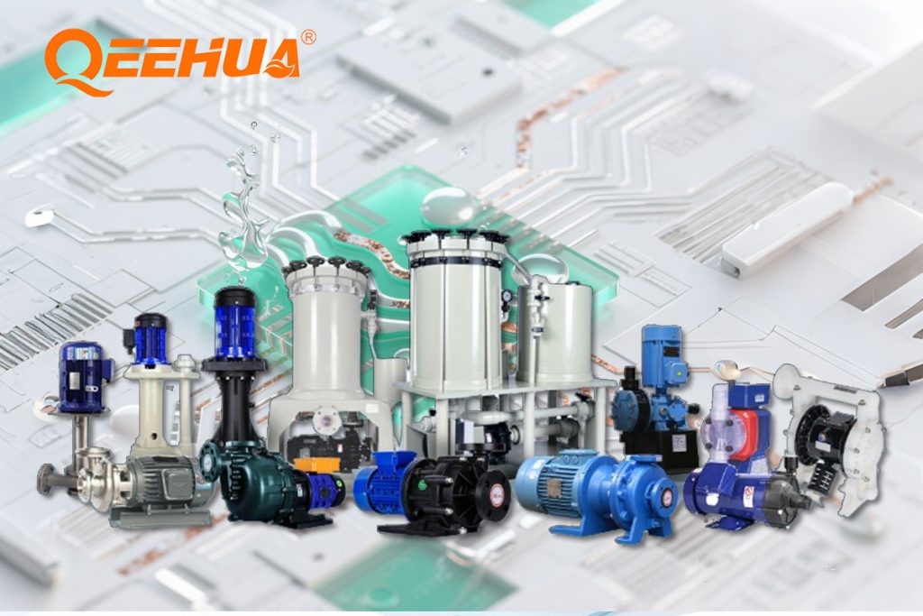
QEEHUA supplies magnetic drive pumps, vertical pumps, plastic centrifugal pumps, and chemical filter systems used in PCB, electroplating, surface treatment, environmental protection, semiconductor-related wet processes, and new energy applications. For PCB developer, etching, cleaning, PTH, electroless copper, nickel-gold, and filtration loops, the best fit depends on liquid chemistry, solids level, suction arrangement, flow, head, operating temperature, and contamination tolerance.
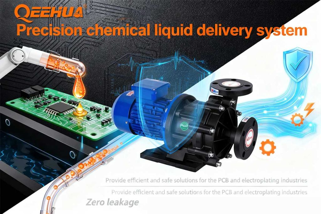
If leakage control and chemical containment are the priority, a sealless magnetic drive pump can be a strong choice. If filtration quality is the process bottleneck, review filter media, pump flow, housing venting, and cartridge sealing together. For dry-run and electrical protection, include pump protection planning before the line is handed over to production.
When asking QEEHUA to review a gas-binding or no-flow problem, send the chemical name and concentration, temperature, tank level range, suction pipe diameter and length, pump model, filter model, cartridge micron rating, normal and abnormal pressure readings, and a short video of the startup and venting sequence. For application support, contact info@qeehua.com.
For a related troubleshooting angle, review PCB Etching Pump Running Backwards: Symptoms, Risks, and Phase-Sequence Fixes before finalizing the pump decision.
For a related troubleshooting angle, review Magnetic Drive Pumps: The Ultimate Guide to Working Principles & Selection (2026) before finalizing the pump decision.
FAQ
Is gas binding the same as cavitation?
No. Gas binding means the pump contains too much air or gas to move liquid properly. Cavitation is bubble formation and collapse caused by low pressure relative to vapor pressure. In PCB lines the two can occur together, because suction starvation, vortexing, and hot chemistry can create both gas entrainment and cavitation-like noise.
Why does the pump lose flow after changing filter cartridges?
The most common reason is trapped air in the filter housing or discharge line. Vent the filter from the highest point until liquid flows without bubbles, then restart gradually and confirm that pressure and flow stabilize together.
Can a magnetic drive pump run through gas binding without damage?
It should not be treated as safe. Magnetic drive pump internals depend on pumped liquid for lubrication and heat removal. Repeated no-flow or gas-bound operation can overheat bushings, thrust surfaces, impeller parts, or magnetic components.
Why does developer solution cause more air-binding complaints than clean water?
Developer chemistry can foam, release CO2, crystallize at low temperature or stagnant points, and carry film residues. These factors increase gas pockets, suction restriction, and unstable filtration compared with clean water testing.
What should be checked before buying a replacement pump?
Check suction layout, tank level, venting, filter pressure, cartridge condition, chemistry, and material compatibility first. If the root cause is vortexing, foam, or filter gas lock, replacing the pump with the same installation conditions may repeat the failure.
Conclusion
PCB developer pump gas binding is usually a system problem: suction design, liquid level, foam, reaction gas, filter venting, and pump protection all interact. The fastest path to stable production is to vent the system correctly, stop air entry at the suction side, keep the pump flooded, match pump and filter capacity, and choose materials and protection devices that suit the actual wet process chemistry. QEEHUA can help OEMs and PCB plants review the pump-filter loop so the selected equipment supports stable flow, cleaner chemistry, and lower process risk.
