PCB pump suction piping air pockets happen when the suction line, tank outlet, reducer, or pump position lets gas collect before the impeller. The pump may still run, but the wet process flow becomes unstable. In etching, developing, micro-etching, rinsing, and filtration loops, that unstable flow can cause uneven spray pressure, poor chemical exchange, local under-etching, residual film, and repeated pump alarms.
This problem is close to gas binding, but the root cause is usually different. A gas-bound pump may be caused by foam, reaction gas, or poor priming. Suction piping air pockets usually start with installation geometry. For a related process-risk view, see QEEHUA’s guide on PCB developer pump gas binding.
For B2B buyers and maintenance teams, the important question is not only whether the pump has enough rated flow. The line must also feed the pump with a full, stable, air-free liquid column. If the suction side creates a gas pocket, even a correctly sized pump can behave like the wrong pump.
Why Suction Air Pockets Matter in PCB Wet Lines
PCB wet process tanks often use compact layouts. Equipment builders must fit pumps, filters, spray headers, valves, drain lines, and service space into a tight frame. That pressure can lead to short suction lines, upward pipe runs, small pipe diameters, high pump positions, or reducers that trap air.
Once air collects on the suction side, the pump no longer receives a continuous liquid stream. Small bubbles may pass through the impeller. Larger pockets can move as slugs. Either condition changes flow, head, vibration, noise, and pressure readings.
In a PCB etching line, that matters because spray uniformity controls line width. If flow falls on one side of a spray bar, the board may see different copper removal rates. In a developer line, low flow can leave film residue. In chemical cleaning or micro-etching, weak circulation can reduce hole exchange.
Symptoms Operators Notice First
The first symptom is often a flow pattern that changes without a clear process change. The spray header looks strong after startup, then weakens. A pressure gauge may swing. The pump may sound normal for a few seconds, then noisy.
Operators may also see bubbles returning to the tank. The pump casing can feel hotter than expected. A magnetic drive pump may lose flow even though the motor is energized. A mechanical seal pump may start leaking sooner because vibration and dry spots stress the seal faces.
These symptoms can be mistaken for a clogged filter. They can also look like water hammer after a valve change. That is why teams should compare the suction layout with the outlet-side checks in QEEHUA’s article on PCB wet process water hammer.
| Observed symptom | Likely suction-side cause | PCB process risk | Practical check |
|---|---|---|---|
| Flow rises and falls after startup | Air pocket moves through the pump as a slug | Uneven spray pressure and local etching variation | Check high points, reducers, and vent points on the suction run |
| Gauge pressure swings during normal operation | Vortex or insufficient submergence pulls air into the inlet | Unstable chemical exchange in holes and fine features | Check liquid level, inlet depth, and anti-vortex baffle position |
| Pump is noisy but the filter is clean | Suction pipe is too small or has too many elbows | Lower circulation rate and higher vibration | Compare suction pipe size with pump inlet size |
| Flow drops after filter maintenance | Filter housing or suction line was not fully vented | Residual particles or film stay in the bath longer | Vent the filter from the highest point before full operation |
Root Causes in Suction Piping and Tank Layout
Upward Suction Piping Creates a Gas Pocket
A suction pipe should not climb upward and then fall into the pump. The high point becomes a gas pocket. Local QEEHUA pain-point files describe this as a common PCB etching problem: an upward suction run forms trapped air, and the etching flow becomes unstable.
A safer layout keeps the suction run short and smooth. It should slope so air can move away from the pump or reach a planned vent point. KSB describes this same risk in its explanation of air pocket formation in pump piping. If the existing frame cannot be changed, add a corrosion-resistant vent at the high point and make it part of startup SOP.
The Suction Pipe Is Smaller Than the Pump Inlet
A small suction pipe increases velocity and friction loss. It also makes the pump more sensitive to air. QEEHUA’s local troubleshooting table recommends that the suction pipe should be at least the pump inlet diameter. It also recommends fewer elbows and a short suction route.
If a reducer is required, the transition must avoid air trapping. In horizontal suction piping, engineers often use an eccentric reducer so gas cannot sit at the top of a concentric reducer. This detail is small, but it has a large effect on pump stability.
Tank Submergence Is Too Low
If the tank outlet or pump inlet is too close to the liquid surface, a vortex can pull air into the suction line. Hydraulic Institute submergence guidance treats pump intake depth as a design issue, not a cosmetic layout detail. QEEHUA’s local notes also call for enough immersion depth and an anti-vortex baffle when liquid level changes during production.
Filter Housings Are Not Vented from the Highest Point
Chemical filters can hold air after cartridge replacement. If the vent valve is not at the highest point, the housing may keep a hidden air pocket. The filter may look full from the outside, but the circulation path is still unstable.
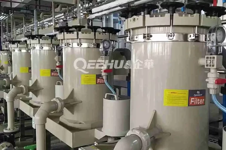
That is also why filter selection and pump selection should be reviewed together. If filtration is the main bottleneck, the article on PCB wet process filtration and chemical filter pump selection gives a broader system view.
Inspection Checklist for Maintenance Teams
Start with the visible layout. Do not replace the pump before checking the suction path. A new pump will not fix an air pocket that the piping keeps creating.
Check the Suction Pipe Route
Trace the suction line from the tank outlet to the pump. Mark every high point. Look for an upward climb, a sagging section, a reducer, a valve, or an elbow close to the pump. Each point can trap gas or disturb inlet flow.
Check Liquid Level and Inlet Depth
Review the lowest real operating level, not only the normal tank level. If the pump inlet becomes shallow during production, add level control or change the outlet position. For dry-run risk at low liquid level, use the checks in QEEHUA’s guide to PCB wet process pump dry running protection.
Check Venting During Startup
Open the high-point vent until liquid flows steadily without bubbles. Then start the pump at a controlled condition. If bubbles return after a few minutes, the system is still pulling air in or releasing trapped gas from another high point.
Check Seals and Joints Under Suction
A suction-side joint can admit air without showing liquid leakage. Inspect threaded joints, unions, gaskets, valve stems, and O-rings. If swelling or chemical attack is suspected, compare the material logic in QEEHUA’s article on chemical pump O-ring swelling and seal leakage.
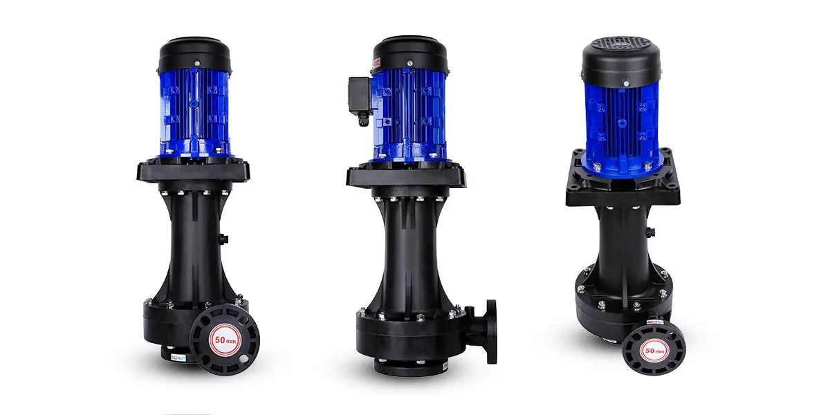
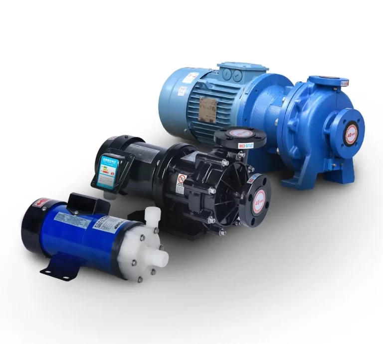
Where QEEHUA Pumps Fit
QEEHUA can support PCB wet process circulation with magnetic drive pumps, centrifugal pumps, vertical pumps, and chemical filter systems. The best choice depends on tank layout, liquid level, corrosion risk, required flow, filtration load, and whether the system needs seal-free containment.
If leakage control is the main priority, a sealless magnetic drive design is often a strong fit. QEEHUA’s magnetic pump product range includes chemical pump options for corrosive wet process liquids. The final selection should still confirm suction layout, material compatibility, flow, head, temperature, and protection devices.
Need help reviewing a PCB pump suction layout? Send the tank level, suction pipe diameter, pump model, liquid, temperature, and photos of the suction run to info@qeehua.com. QEEHUA can help check whether the issue is pump sizing, air pocket formation, venting, material compatibility, or filtration load.
FAQ
Why does my PCB etching pump lose flow even when the filter is clean?
A clean filter does not rule out suction-side air. Check for an uphill suction pipe, shallow tank outlet, vortex, loose suction union, or trapped air in the filter housing before replacing the pump.
Should a PCB wet line use an eccentric reducer on the pump suction side?
Use an eccentric reducer when the suction pipe is larger than the pump inlet and the layout could trap gas. The goal is to keep the suction path liquid full and prevent a high air pocket near the pump.
How much liquid depth is needed above a PCB pump suction inlet?
The safe depth depends on flow rate, inlet diameter, tank shape, and turbulence. As a practical check, confirm the lowest operating level, prevent vortex formation, and add an anti-vortex baffle when the inlet is near the surface.
Can a suction air pocket cause PCB under-etching or residual film?
Yes. Air pockets can reduce circulation and create unstable spray pressure. That can weaken chemical exchange on the board surface or inside holes, especially in fine-line etching and developer sections.
What should an OEM send before asking QEEHUA to check a suction piping problem?
Send the pump model, liquid name, temperature, suction pipe diameter, pipe route photos, tank liquid level range, filter model, and a short video of the pressure or flow fluctuation.
