

Magnetic Drive Pump Magnet Decoupling: Causes, Safe Restart, and Prevention
A magnetic drive pump can sound as though it is running normally while the liquid has stopped moving. The motor turns, the outer magnet turns, and the impeller-side magnet has fallen out of synchronism. Operators may call this magnet slip, pull-out or decoupling. The name matters less than the response: stop the pump in a controlled way, find the load that exceeded the available coupling torque, and do not keep attempting restarts until the hydraulic and mechanical checks are complete.
Decoupling is not automatically proof that the magnets have failed. It is a warning that the magnetic coupling could not transmit the torque demanded at that moment. The initial event may be a closed valve, a blocked filter, a jammed bearing, solids in the pump, a dense cold liquid, an unexpected pressure rise, or heat from running without enough internal circulation. If the pump is repeatedly run in this condition, the first protective event can become an expensive repair involving the magnet set, containment shell, internal bearings or impeller assembly.
This guide is written for chemical-process operators, OEM skids and maintenance teams using sealless magnetic drive pumps. It treats decoupling as a system problem rather than a reason to replace a pump immediately. The goal is to distinguish a one-off upset from a duty-point, liquid, piping, control or internal-parts problem before the next start.
What magnet decoupling means on a chemical pump
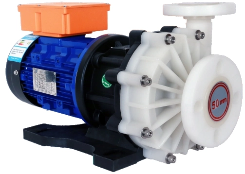
A conventional coupled pump sends motor torque through a shaft and mechanical coupling. A magnetic drive pump sends torque across a stationary containment shell using an outer magnet on the motor side and an inner magnet connected to the impeller assembly. The containment shell keeps the wetted pump side sealed. That is valuable for corrosive, toxic and high-purity liquids, but it means the magnetic coupling has a finite torque capacity.
During normal service, the two magnet sets rotate together at the same speed. When required torque rises above the coupling’s usable limit, the inner assembly can lag and lose its pole-to-pole position. The motor may then accelerate toward its unloaded speed while the impeller stops or turns irregularly. A 2017 technical overview of magnetic drive pumps describes this maximum-torque boundary and notes that operation after decoupling can damage magnet strength through heat. The paper is a useful technical reference, but the correct torque limit and restart method for any installed pump must come from that model’s documentation.

What operators may observe
The practical symptoms are often simpler than the physics. Discharge pressure drops or becomes unstable. Flow indication falls. The motor current may change because the motor is no longer carrying the same hydraulic load. A pump body can become hot if internal flow is lost. The sound can change, although a quiet magnetic drive should never be cleared as healthy by sound alone. On an automatic line, a low-flow, low-pressure, temperature or motor-protection alarm may be the first useful signal.
Do not diagnose decoupling only from one symptom. A blocked suction line, a failed level switch, a broken coupling component, a VFD speed command error or an empty tank can also produce low flow. The field task is to compare motor status, pressure, flow, liquid level, valve position, temperature and the time sequence of alarms. A small record made before resetting an alarm is far more useful than a restart followed by a second unexplained trip.
Why it differs from a simple motor overload
A motor overload relay protects the electrical drive from excessive current. It does not always prove that the impeller has stopped or that the magnet sets remain synchronized. A magnetic drive system therefore benefits from process-side evidence as well: discharge pressure or flow confirmation, tank level permissives, a dry-run device where appropriate, and temperature or power monitoring for the actual service. The QEEHUA guide to PCB pump interlock logic shows how level, flow, pressure and VFD signals can be combined instead of relying on a single switch.
Why torque margin matters more than a catalogue flow number
Decoupling occurs when the torque demanded by the rotating hydraulic assembly is higher than the torque the magnetic coupling can transmit at that speed and temperature. In simplified form:
Required shaft torque: Treq = Pshaft / omega
For a pump, Pshaft = rho x g x Q x H / eta. Here rho is liquid density, g is gravitational acceleration, Q is flow, H is total dynamic head and eta is pump efficiency. Therefore, a higher density, higher head, higher flow or lower efficiency increases the torque the pump requires. The U.S. Department of Energy uses the same hydraulic-power relationship in its pumping-system guidance.
This equation is not a substitute for a magnetic-coupling curve. It explains why operating conditions matter. A pump selected close to the coupling limit for water may have less margin with a denser electrolyte, a colder caustic solution, a high-viscosity batch, a fouled filter, or a discharge line that has acquired additional head loss. The relevant comparison is not motor nameplate power alone. It is the pump’s required torque against the coupling’s rated torque at the actual speed, liquid and temperature.
A simple example for a selection review
Assume a process needs 12 m3/h at 28 m head with a liquid density of 1,180 kg/m3 and estimated pump efficiency of 0.45. Hydraulic power is rho x g x Q x H. With Q converted to 0.00333 m3/s, the hydraulic power is about 1.08 kW. Dividing by 0.45 gives a shaft-power estimate of about 2.40 kW. At 2,900 rpm, angular speed is approximately 304 rad/s, so the estimated shaft torque is about 7.9 N m.
The example is deliberately incomplete. It does not include every internal loss, transient, starting condition or coupling derating factor. Its purpose is to make the data request clear. Before a supplier can judge decoupling margin, they need the real density, temperature, viscosity, flow range, pressure or head range, solids condition, start-up sequence and any situation where a valve may be closed. A bare request for “a 3 kW magnetic pump” leaves the important part of the decision hidden.
Seven causes to separate in the field
Many decoupling investigations go wrong because the team assumes that every loss of flow is a magnet problem. Start with the process condition, then inspect the internal parts only after the line is made safe. The following causes can overlap, so use the order of alarms and operating changes to rank them.
1. Closed, blocked or unexpectedly high-head discharge conditions
A closed discharge valve, a stuck check valve, a plugged filter, a crystallized pipe section or an added restriction can move the pump toward a high-head, low-flow condition. Depending on the pump curve and liquid, internal recirculation and heat rise may follow. The load can become severe enough to pull the magnets out of step. Do not confuse this with the related but distinct problem of magnetic drive pump deadheading. Deadheading is a hydraulic operating condition; decoupling is a loss of torque synchronism that may result from it.
Check valve position and actual downstream pressure before removing the pump. A pressure gauge that reads zero because its impulse line is blocked is not proof that the pump is unloaded. Compare local gauges, transmitter history and valve feedback where available.
2. A dense, viscous or cold liquid outside the original basis
Liquid density drives hydraulic power, and viscosity changes hydraulic losses and pump performance. A chemical line may see a colder overnight batch, higher concentration, solids loading or a formulation change that was never added to the pump data sheet. The pump can then require more torque than it did during a water test. This is common when a system is selected from nominal flow and head but has no defined minimum temperature or concentration range.
Take a real sample and compare it with the design basis. Ask whether the issue appears only at one temperature, after a tank changeover, at the start of a shift or when a particular chemical is used. Those clues are more valuable than immediately increasing motor size. Material compatibility matters too. The QEEHUA article on PPH, PVDF and fluorine-lined magnetic pump materials explains why a liquid review must include temperature and chemistry, not simply acid or alkali labels.
3. Solids, metal particles or bearing seizure
The inner rotor of many magnetic drive pumps relies on the pumped liquid for cooling and lubrication. Abrasive solids, plating debris or metal particles can damage journal bearings, restrict clearances or jam the rotating assembly. QEEHUA’s local electroplating and PCB service notes flag magnet-gap iron particles and inadequate filtration as recurring causes of abnormal operation. This is not a reason to use an undersized strainer that creates its own suction loss. It is a reason to define particle source, size, filter flow capacity and cleaning method.
When the pump is safely isolated and opened under the manufacturer-approved procedure, inspect the wet end, internal bearings, thrust surfaces and magnet area for scoring, embedded particles, discoloration and chemical attack. The separate guide on metal particles in magnetic drive pumps focuses on that contamination pathway. Replacing magnets without removing the source of particles only repeats the failure.
4. Dry running, low internal flow or trapped gas
A sealless pump still needs the internal conditions stated by its design. Starting dry, running with a low tank level, losing prime, drawing a vortex, trapping gas at a high point or operating below the required minimum flow can reduce cooling and lubrication. Heat then changes clearances and can reduce magnet performance. The technical overview cited below specifically calls out dry running, low flow and poor-lubricity liquids as risks to magnetic drive pump bearings and high temperature as a magnet risk.
Check suction submergence, vent points, valve position, strainer differential pressure and tank level. In an automatic installation, inhibit starting on low level where the process allows it. A level switch alone may not prevent a brief dry condition if the suction line drains between batches, so the control logic should reflect actual start-up behavior.
5. Wrong VFD acceleration, speed or protection settings
A VFD can make a chemical pump easier to control, but incorrect parameters can create a transient the hydraulic system was not designed to handle. An aggressive acceleration ramp, a speed command above the approved curve, unstable PID control, minimum-speed operation without adequate cooling flow, or a restart while the line is pressurized can change the torque demand quickly. Review the commanded speed and motor current trend around the alarm, not just the final setpoint.
Use a written parameter record. It should show maximum speed, acceleration and deceleration ramp, minimum permitted speed, dry-run or low-flow response, restart delay and alarm reset authority. The local QEEHUA notes include cases where VFD parameter drift produced unstable chemical circulation. A password-protected parameter set and a commissioning copy prevent a quiet settings change from becoming a pump mystery.
6. High temperature and loss of magnet strength
Heat can be a cause, a result or both. High liquid temperature, internal recirculation, dry running and friction from damaged bearings raise the temperature near the inner components. Permanent magnets have a temperature limit that depends on magnet grade and pump design. Once overheating has weakened a magnet set, the available torque margin may no longer be the same as when the pump was new.
Do not guess the temperature limit from a general online value. Confirm the actual pump’s permitted liquid temperature, containment-shell material, magnet grade and derating guidance. Check whether the event occurred after a process heating change, a blocked cooling path or multiple rapid restart attempts. If disassembly shows heat discoloration or abnormal clearances, involve the pump supplier before returning the unit to service.
7. Pipework changes and pressure transients
New elbows, undersized valves, a fouling filter, a long discharge extension or a changed spray header can move the operating point. Fast valve closure and process transients can also create momentary pressure demand that is not visible in a single manual gauge reading. Review the current piping against the commissioning drawing. The detailed QEEHUA guide on plastic chemical-pump pipe head loss helps turn fittings, valves and pipe diameter into a checkable head-loss calculation instead of an assumption.
A safe restart sequence after suspected decoupling
A restart is not a test method. Repeated starts can add heat and friction while the inner parts are not rotating correctly. Before any inspection or reset, isolate electrical energy and process energy under the site’s procedure. The U.S. Occupational Safety and Health Administration’s lockout/tagout requirement is the general reference for controlling hazardous energy. Chemical isolation, draining, venting and personal protective equipment remain site-specific requirements.
Controlled restart checklist
- Stop the pump and preserve the alarm history, VFD speed, motor current, flow, pressure and tank-level evidence.
- Lock out electrical supply, close and isolate process valves as required, depressurize and drain safely.
- Verify liquid level, suction condition, valve alignment, filter status and downstream restrictions before opening equipment.
- Inspect externally first. Look for hot areas, leaks, damaged supports, abnormal vibration marks and incorrect actuator positions.
- Only open the pump if the model procedure, chemical controls and qualified personnel permit it. Inspect internal bearings, impeller freedom and contamination source.
- Correct the root cause, refill or prime the pump as required, vent trapped gas and restore the planned valve position.
- Restart at the approved speed and observe pressure, flow, current and temperature. Record the result rather than clearing the event without a note.
When the pump should not be restarted
Do not restart if the casing is hot without a clear explanation, the pump has run dry, the chemical is incompatible with the inspection plan, there is evidence of a jammed rotor, containment-shell damage is suspected, or the cause is an unresolved blocked line. Do not use repeated electrical resets to “pull the magnets back in.” A successful reset does not erase possible thermal damage or an uncorrected process restriction.
What a controlled return to service looks like
After the cause is corrected, bring the pump back to the documented operating point. Verify the suction source is available, the pump is filled when required, vents are closed after proper venting, the discharge path is open and the VFD is at the approved starting speed. Watch a stable period long enough to see the process settle. Log actual flow or pressure against the expected value. A pump that starts but cannot sustain the flow after a few minutes still has a system problem to solve.
Design and control measures that keep margin in the system
Prevent decoupling with a selection basis, piping arrangement and control scheme that do not ask the coupling to transmit an unplanned load. Begin with the liquid and operating envelope. Define normal, minimum and maximum density, viscosity, temperature, solids, flow, head and frequency of starts. Include abnormal but credible cases: a dirty filter, a cold batch, a partly closed valve, one pump out of two unavailable, a high tank level, or a VFD at maximum speed.
Specify the coupling with a clear duty envelope
Ask for a pump curve, power curve and magnetic-coupling rating that identify the proposed liquid and speed range. Confirm whether the manufacturer applies temperature or speed derating. For a variable-speed system, make sure the review includes the highest approved speed and the most demanding liquid, not only the normal setpoint. For a system with a bypass, confirm where it returns and whether minimum internal flow is maintained during low-demand operation. The related minimum-flow bypass guide explains why a recirculation line needs an actual thermal and hydraulic purpose rather than a nominal valve.
Use measurements that prove flow, not just motor rotation
For critical chemical circulation, use a practical combination of process signals. A low-level permissive can prevent an empty-tank start. A low-flow or low-pressure alarm can detect lost circulation. Motor current or power can show a load change. Temperature can reveal internal heating. The best combination depends on the service and the cost of a missed event. A simple line may use level plus pressure. A high-consequence line may use level, flow confirmation, motor protection and a timed shutdown sequence.
Keep contaminants and air out of the wet end
Install filtration based on the pump’s solids tolerance and the process contamination source, not on a generic mesh number. Place a differential-pressure indication where maintenance can see it. Make cleaning responsibility explicit. In a plating or etching line, identify whether particles come from the tank, pipework, fixtures, a filter breakthrough or corrosion products. For ferrous contamination near a magnetic drive, the source can matter as much as the size of the particles.
At suction, avoid high points that trap gas and pipe arrangements that starve the pump. Give a self-priming or non-self-priming design the installation it requires. A pump can be mechanically intact and still decouple after gas ingestion, so venting and tank-level design deserve the same attention as a motor protection setting.
Troubleshooting records and a decision table
Decoupling investigations become repeatable when the first responder records the same facts each time. Write down the time, tank or batch, chemical, temperature, VFD command, current, pressure, flow, level, valve position, filter reading and alarm order. Add photographs of local gauges and the pipe arrangement if a modification was recently made. These details make it possible to compare two events instead of relying on a memory of “the pump stopped again.”
| Observed pattern | Likely checks first | Do not do | Useful evidence |
|---|---|---|---|
| Motor runs, pressure and flow fall suddenly | Valve position, downstream restriction, flow or pressure history, VFD speed | Repeat start without checking the line | Trend from one minute before the alarm |
| Event follows a cold batch or concentration change | Density, viscosity, temperature and actual operating head | Assume the water-test duty still applies | Batch record and laboratory data |
| Event follows filter maintenance or a dirty-filter alarm | Filter installation, differential pressure, bypass position and solids source | Remove filtration without a contamination plan | Before/after filter pressure and inspection photos |
| Repeated event with heat or abnormal noise | Dry running, internal bearing condition, magnet condition and containment shell | Keep resetting the overload | Temperature, alarm count and qualified inspection record |
| Event only at certain VFD speeds | Speed curve, acceleration ramp, control loop and piping response | Raise maximum speed as a trial fix | VFD parameter export and process trend |
Give the final report a clear conclusion: confirmed cause, contributing conditions, checks completed, parts inspected, settings changed, and criteria for monitoring the next run. If the cause cannot be confirmed, say so and run a controlled test with the needed instrumentation. A vague conclusion such as “magnetic problem” can lead to replacing the pump while the blocked filter, cold liquid or improper VFD ramp remains in the system.
Has a magnetic drive pump lost flow while the motor kept running? Send QEEHUA the pump model, liquid name and concentration, temperature range, flow and head target, piping sketch, alarm trend and photos of the filter or suction arrangement at info@qeehua.com. We can review whether the likely issue is coupling margin, operating condition, internal contamination or control logic before a replacement is selected.
FAQ
What is magnetic drive pump decoupling?
It is the loss of synchronism between the motor-side outer magnet and the impeller-side inner magnet because the pump requires more torque than the coupling can transmit under that condition.
Can a magnetic drive pump be restarted after decoupling?
Only after a controlled check of liquid level, valve alignment, suction condition, restrictions, internal condition where required and the original alarm evidence. Repeated resets without finding the cause can add heat and damage.
Does a larger motor prevent magnet decoupling?
Not necessarily. The relevant limit is the magnetic coupling torque at the actual speed and temperature, together with pump hydraulic demand. A larger motor does not automatically increase coupling capacity.
Can a clogged filter cause decoupling?
It can contribute by changing the system resistance, starving the pump or creating abnormal operating conditions. Check filter differential pressure, valve arrangement and suction conditions before assuming the magnet set is defective.
What signals should protect a critical magnetic drive pump?
A suitable scheme often combines tank level, flow or pressure confirmation, motor current or power and temperature, with delays set during commissioning. The exact combination should match the liquid, line layout and consequence of lost flow.
