

A chemical pump can have the correct flow, head and wetted material, then still give trouble on its first week of service because the base is uneven, the anchor bolts are loose, or the pipework pulls the pump out of position. The first signs are often modest. A coupling runs warm. A pressure reading moves more than expected. The motor current is higher after the piping is connected than it was during a bench test. Left alone, those signs turn into vibration, leaking joints, worn bearings, cracked plastic flanges or a pump that no longer reaches its duty point.
Foundation and alignment work should happen before chemical is introduced. This is especially important for corrosive systems, where the pump may sit beside a tank, filter, scrubber or containment tray and the connecting plastic pipe can expand, sag or impose side load as it warms. QEEHUA’s local electroplating and PCB installation notes identify uneven bases, loose anchor bolts, poor coupling alignment and unsupported pipework as repeat causes of early pump trouble. A practical pre-start check prevents many of those failures.
This article is for equipment builders, maintenance teams and buyers who need to inspect a chemical pump installation before commissioning. It covers horizontal centrifugal pumps, magnetic drive pumps with external motor arrangements, self-priming pumps and vertical pumps on fabricated frames. A vertical pump does not have the same shaft coupling check as a separately coupled horizontal pump, but it still needs a level, supported structure and pipework that does not pull on the nozzle.
Why the base matters before the pump runs
A pump and motor are intended to work in a defined position. The rotating parts, bearings, seals and magnetic coupling all depend on clearances that change when the base twists or the piping applies a constant side force. The installation can look acceptable when it is stopped. Once the motor starts, vibration and temperature reveal the problem.
The foundation has four jobs. It gives the equipment a flat reference surface. It holds the pump in place under starting and operating loads. It limits movement caused by vibration. It gives maintenance staff a repeatable position when the pump, motor or coupling guard is removed and reinstalled.
For an OEM skid, the fabricated base frame becomes the practical foundation. The same checks apply. Put the skid on a level support, shim it at the designed points and tighten the fixing bolts only after the frame is sitting without twist. Do not use the suction or discharge pipe to pull a frame into place. That transfers the installation error directly to the pump casing.
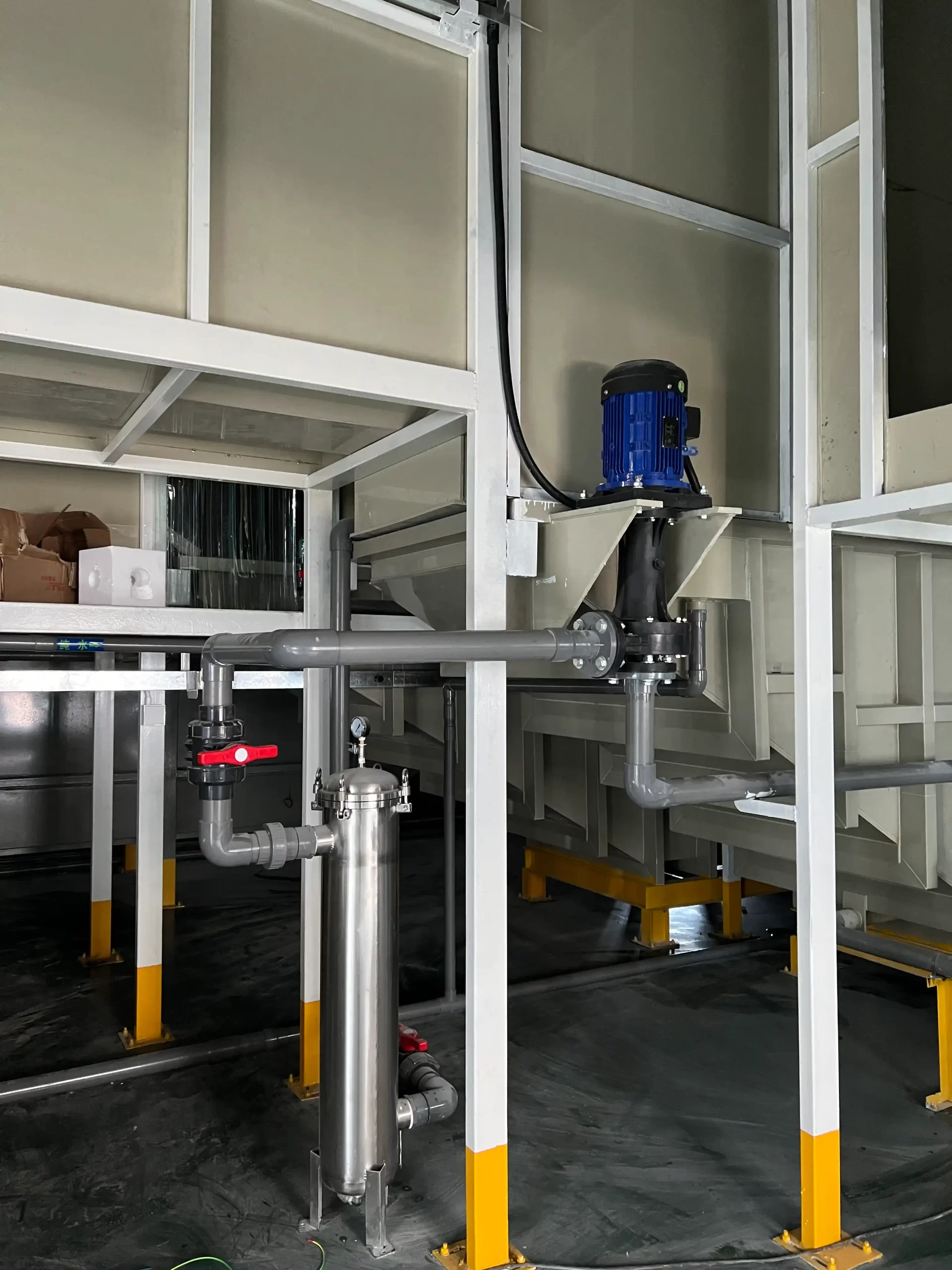
A good base does not compensate for a wrong hydraulic design. It only keeps the selected pump in the position used for its performance and mechanical checks. If the actual flow is low after installation, compare the system with the pipe head-loss checks for plastic chemical lines. A pipe restriction or a partly shut valve can look like a mechanical problem when it is actually a duty-point problem.
Common field symptoms
Loose anchor bolts often show up as a repeating vibration that changes when the line starts or stops. Misalignment can bring a hot coupling guard, bearing noise or seal trouble. Pipe load may be easier to spot when a union is loosened. If the pipe shifts away from the pump nozzle as soon as the union is released, the pipe was forcing the pump into position.
Plastic pipe systems add another variable. A line that was straight at ambient temperature can move after warm liquid arrives. Support spacing, expansion allowance and flexible connections must be reviewed with the pump position. The recent QEEHUA guide on plastic chemical-pump piping expansion explains why this movement should be handled by the line instead of the pump nozzle.
Foundation and anchor-bolt checks
Start before the motor is energized. Empty the pump if possible, isolate the system and remove enough guarding to inspect the base safely. Use the site lockout procedure when work is near energized equipment. OSHA’s control-of-hazardous-energy rule is a useful reference for the lockout principle. Chemical systems also need their own drain, depressurization and protective-equipment steps.
Check the support surface first
Inspect the concrete pad, steel platform or skid support for corrosion, settlement, cracked grout, missing shims and standing chemical residue. The QEEHUA local installation workbook uses a practical foundation flatness target of no more than 0.1 mm per metre for pump installation. Treat that figure as a field target, not as a replacement for a project specification or the pump manufacturer’s installation drawing.
Place a precision level across the base in more than one direction. A single reading along the motor axis is not enough. Check across the base, along the base and diagonally if the frame is long. If one corner is unsupported, correct the support before tightening bolts. Tightening a twisted base can preload the casing and change alignment once the fasteners are fully torqued.
Inspect anchor bolts without guessing
Anchor bolts should be clean enough to inspect, seated in the correct holes and tightened in a balanced pattern. Look for stretched threads, corroded nuts, missing washers, crushed polymer pads and movement marks around the bolt head. A paint witness mark on the nut and base can make later movement easy to see during routine inspection.
Tighten bolts in a cross pattern when the base has several anchors. The aim is even contact, not maximum force on the nearest bolt. Use the torque stated in the equipment drawing or site fastener procedure. Do not invent a torque value from bolt diameter alone because material grade, lubrication, washers and base design change the required value.
| Check point | What to inspect | What can go wrong if missed | Useful record |
|---|---|---|---|
| Base support | Level at several points, shims seated and no rocking | Frame twist and changed shaft position | Level readings and shim locations |
| Anchor bolts | Thread condition, washers, cross-pattern tightening and witness marks | Movement, vibration and loose equipment | Fastener size, grade and approved torque source |
| Grout or frame | Cracks, corrosion, chemical residue and unsupported corners | Loss of stiffness or delayed settlement | Photos before startup |
| Pipe supports | Independent hangers, guides and expansion allowance | Nozzle load, flange leakage and casing distortion | Support locations and pipe temperature range |
Alignment and pipe-load checks
Alignment is most relevant when the pump and motor are connected through a coupling. It is not a one-time factory activity. Transportation, base installation, bolt tightening and piping can all change it. QEEHUA’s local installation notes use a dial-indicator alignment target of 0.05 mm or less for magnetic-cylinder or coupling concentricity. Use the final tolerance in the pump manual when it differs, especially for high-speed or special-duty equipment.
Measure after the pipework is connected
Check alignment after the suction and discharge pipes are connected, supported and filled to the expected operating condition where practical. If alignment is measured before piping and never repeated, the final reading says little about the working installation. This is one reason a pump may pass a workshop run but vibrate at site.
For a flexible coupling, check parallel offset and angular offset using the method approved for that coupling. A dial indicator or laser tool can give a repeatable result. A straightedge is useful as a quick screen, but it is not enough for a final acceptance record on a critical corrosive-duty pump.
Pipework must stand on its own
Before final bolting, loosen a nearby flange or union only when the line is isolated, drained and safe to open. The pipe should remain in place. If it moves sideways, vertically or rotates to meet the nozzle, add or correct supports. Do not force a plastic flange closed with bolts. Plastic faces can distort and later leak after temperature changes.
There is a simple field check. Record the alignment with the pipe connected. Support the pipe properly and remove the nozzle load. Measure again. A meaningful change tells the team that the pipe was loading the pump. Fix the supports, guides, expansion joint or pipe route, then repeat the alignment check.
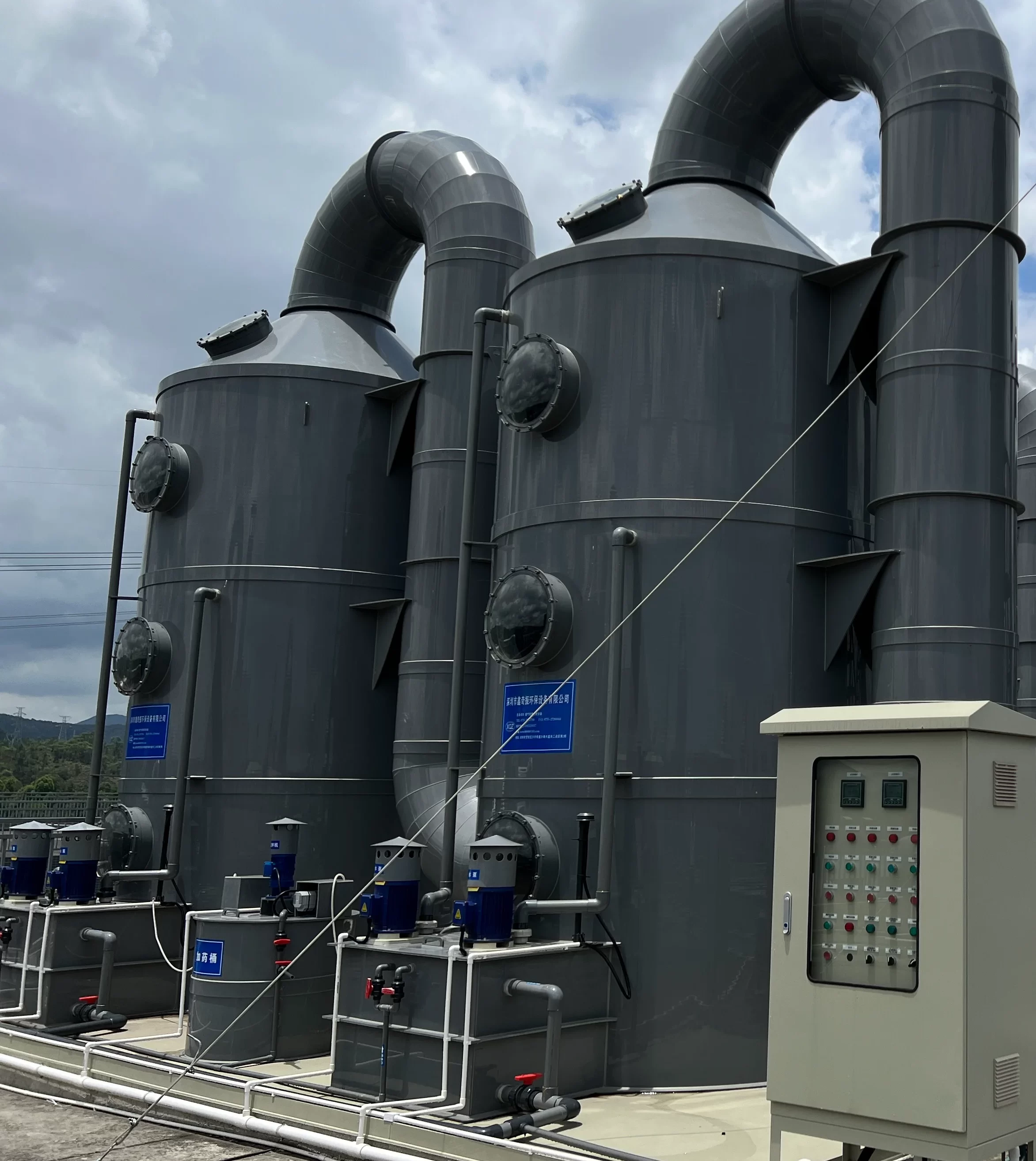
For vertical equipment, inspect column plumb, mounting plate stiffness, tank or platform support, and the route of the discharge line. A vertical pump may not have a separate motor coupling to align, but a tilted support or a heavy unsupported discharge pipe can still create vibration and stress at the mounting plate. The vertical centrifugal-pump overview is a useful product-context reference when deciding whether a vertical arrangement fits the tank geometry.
Do not hide hydraulic problems behind alignment work
Alignment will not cure suction air, a clogged strainer, wrong impeller diameter or a blocked discharge valve. It prevents a separate mechanical problem. When an installation has both low flow and vibration, check the hydraulic condition and the base condition in parallel. A pump that is starved at suction can vibrate even when alignment is good.
A field startup sequence
Once the base, bolts and pipe supports pass inspection, use a controlled startup. Start with a clean and safe system. Confirm the pump chamber is filled when the pump design requires priming. Confirm the suction valve is open, the discharge condition matches the startup procedure and the filter or strainer has been vented. The commissioning article for PCB chemical-pump systems gives related rotation, leak and instrumentation checks.
Record a cold baseline
Before starting, note the base condition, bolt witness marks, coupling guard condition, oil or grease condition where applicable, valve positions and visible leakage. Record the expected liquid, concentration, temperature, flow and head. These records make later troubleshooting faster because the team can compare an abnormal condition with a known starting point.
Start at the planned operating condition
Watch the pump during the first minutes. Listen for repeated rattling, rubbing or a change in sound as the line fills. Check current, discharge pressure, flow indication and leaks at flanges, unions and instrument connections. Do not put hands near rotating parts or remove a coupling guard while the machine is running.
After the system reaches normal temperature, repeat the visual check. Warm plastic pipe can move. A support may settle. A union that looked dry during a water test may show chemical residue after the real liquid is introduced. Recheck coupling alignment during the first planned shutdown when the service is critical or the piping temperature changes substantially.
Recheck after thermal movement and the first maintenance stop
The first warm run is a useful point to inspect the installation again. Compare the anchor-bolt witness marks with the original photos. Look under the base for new chemical residue or a support that has settled. Check whether a plastic line has moved toward a nozzle as it reaches operating temperature. A small movement at a long pipe run can become a large load at a close-coupled pump connection.
Flexible connectors deserve the same review. They are used to absorb controlled movement and vibration. They are not a way to bridge a large pipe misalignment or to hold up a line with missing supports. If a connector is already stretched, compressed sideways or twisted at ambient temperature, it has little movement left when the liquid heats up. Correct the pipe support and guide arrangement first.
After a coupling, bearing, motor or seal repair, repeat the alignment check instead of relying on the previous report. A replacement motor can have a different foot height. New shims can settle after the first run. A maintenance team should record the measurement before and after final bolt tightening, then check it once the lines have returned to normal temperature. This does not require a long shutdown. It requires a planned inspection point and a record that the next technician can understand.
Watch the evidence from the pump rather than one number in isolation. A slight current increase can be normal when liquid density changes. A current increase paired with new vibration, a hotter coupling guard or a flange that begins to weep needs investigation. Shut down safely before correcting the base, pipework or alignment. Do not continue to run a chemical pump while the motor, coupling or support structure is visibly moving.
Keep service access in the inspection. A base may be level, but a pump is still difficult to maintain if a guard, drain plug, vent, coupling bolt or instrument cannot be reached without standing on pipework. Make sure a technician can remove the guard, use a torque wrench and inspect the underside of the casing without moving supports. Good access reduces the chance that a hurried repair leaves a bolt loose or puts a pipe back under load.
Use a short follow-up interval. On a new line, inspect the base after the first shift, after the first week of normal operation and after any piping modification. This is a better use of maintenance time than waiting for a noise complaint. The record should say whether bolt witness marks moved, whether the pipe supports remained in contact, whether the coupling area stayed clean and whether the measured operating values remained close to the startup baseline.
When several pumps share one platform, label the readings by pump and by operating mode. One quiet pump can otherwise hide a second pump that is moving or overloading.
Practical acceptance sequence
- Confirm the base is level and every support point carries load.
- Verify anchor bolts against the approved drawing and mark the final position.
- Measure coupling alignment after the pipes are connected and supported.
- Verify that a loosened safe union or flange does not release pipe movement onto the pump.
- Record cold current, pressure, flow and vibration observations.
- Repeat the visual inspection after the line reaches working temperature.

What an OEM or plant should record
Installation quality becomes harder to prove once the pipe insulation, guards and chemical residue hide the original condition. Keep a short commissioning record. It does not need to be complicated. Photos of the base, supports and nameplate are useful. Include the pump model, motor data, liquid, temperature range, pipe material, support arrangement, bolt check, alignment result and first operating readings.
For a customer acceptance file, separate mechanical acceptance from hydraulic acceptance. Mechanical acceptance includes the base, bolts, coupling, guard and pipe support. Hydraulic acceptance includes flow, head or pressure, valve arrangement, filter condition and the operating point. QEEHUA’s chemical-pump factory acceptance test checklist can help an OEM structure the pre-shipment part of that record. The site installation record should then confirm what changed after transport and final pipe connection.
When a pump has to be removed later, repeat the same record after reinstallation. A new bearing, motor or coupling part can be installed correctly and still fail early if the base has moved or the piping is still carrying weight. The repeat record protects the maintenance team from replacing parts without correcting the installation cause.
If your corrosive-liquid pump is vibrating, leaking at a flange or showing changed current after pipe connection, send QEEHUA the pump model, liquid, temperature, base photos, pipe layout and available alignment readings at info@qeehua.com. Our team can help separate a foundation, pipe-load or hydraulic issue before a replacement pump is specified.
FAQ
Should a chemical pump be aligned before or after piping is connected?
Make a preliminary alignment before piping, then perform the final alignment after suction and discharge lines are connected and independently supported. The final check shows whether pipe load has moved the pump or motor.
Can plastic piping pull a chemical pump out of alignment?
Yes. Unsupported pipe, poor expansion allowance or a forced flange connection can impose side load on the nozzle. The risk increases when hot liquid changes the pipe length.
What is a practical warning sign of pipe load on a pump?
When a safely isolated nearby union or flange is loosened, the pipe should stay in position. Movement toward or away from the nozzle indicates that the pipe was applying load and needs better support or routing.
Do vertical chemical pumps need foundation checks?
Yes. Vertical pumps still need a level, stiff support and discharge piping that does not pull on the mounting plate. Check plumb, mounting bolts, tank or frame stiffness and service access.
What should be recorded during chemical pump commissioning?
Record the pump and motor details, liquid and temperature, foundation condition, alignment result, pipe-support arrangement, cold and warm operating readings, and photos of any abnormal vibration or leakage.
