

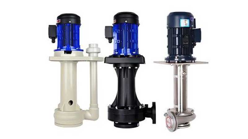
Direct Answer: Commission the Pump as a System, Not as a Motor Test
A chemical pump on a PCB wet process line is ready for production only after four conditions are confirmed: the pump and wetted materials match the bath, the piping and tank provide stable liquid supply, the motor turns in the correct direction, and the installed system delivers the required flow and pressure while every protection interlock works. A brief motor jog is only one check. It is not a commissioning result.
A defensible sequence is document review, mechanical inspection, controlled filling and venting, rotation confirmation, a low-risk first start, hydraulic measurement, protection-trip testing, and a signed operating baseline. This order reduces the chance of starting an empty pump, opening the wrong valve, or accepting a pump that reaches pressure but not process flow. QEEHUA’s guide to low-level dry-running protection explains why liquid level must be treated as an operating input rather than an operator assumption.
Commissioning rule: use the pump supplier’s installation and start-up instructions for the exact model. The checklist below defines the evidence to collect; it does not replace model-specific valve, priming, rotation, or minimum-flow limits.
Use Four Acceptance Gates
A practical commissioning plan separates checks that are often mixed together. Each gate must pass before the next one begins. This prevents a good electrical test from masking a bad suction layout, or a stable pressure gauge from masking inadequate flow at the process header.
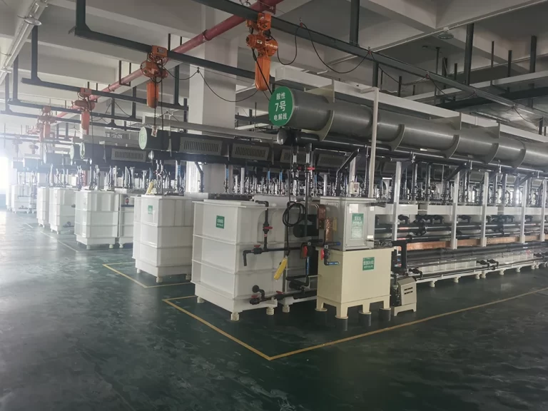
Checks Before Power Is Applied
Start with the approved pump data sheet and piping and instrumentation diagram. Confirm the model, motor voltage and frequency, design flow, total dynamic head, liquid temperature, specific gravity, material code, seal or bearing materials, and allowable operating limits. If the bath chemistry changed after purchase, stop and recheck compatibility. A material that works in a dilute, cool solution may not be suitable at higher concentration, temperature, or with mixed contaminants.
Inspect the installation without energizing the pump. The base must be stable. Pipework must be supported independently so nozzle loads do not distort the casing. Suction piping should avoid high points that trap air. Tank outlets, strainers, vents, drains, bypasses, and check valves must match the drawing. Remove transport plugs and temporary covers. Confirm that flushing debris cannot enter bearings, an impeller, or a magnetic coupling.
- Verify pump tag, rotation arrow, motor nameplate, voltage, frequency, phase, and protective-device settings.
- Confirm the suction valve, discharge valve, bypass, vent, and drain positions against the approved start-up procedure.
- Check that the tank has enough liquid for flooded suction or the specified priming condition.
- Confirm guards, earthing, cable glands, emergency stop, local isolator, and accessible lockout points.
- Record clean filter condition, cartridge rating, valve lineup, and initial differential pressure.
- Make sure gauges, flow instruments, level switches, and pressure switches have current calibration status.
Electrical rotation must be checked by the authorized team using the shortest safe method allowed by the pump manual. Some pumps can be jogged only after they contain liquid. Do not assume an empty pump can tolerate a rotation test. If the direction is wrong, isolate power before correcting phase sequence. The QEEHUA article on a PCB etching pump running backwards lists typical symptoms and phase-sequence checks.
Run a Controlled First Start
Fill and vent the pump and suction line according to the exact pump design. Flooded-suction magnetic and centrifugal pumps need a continuous liquid path. A self-priming pump needs the specified initial casing fill. A vertical pump needs the correct tank level and immersion geometry. Never infer one start method from another pump family.
Place one person at the local controls and one at the pump and process header when site rules allow. Start from the approved valve lineup. Watch suction condition, discharge pressure, flow indication, motor current, noise, vibration, and leakage immediately. Stop if flow does not establish quickly, pressure behaves unexpectedly, or the pump sounds dry. Do not keep restarting to see whether it will recover.
Test the low-level, no-flow, high-pressure, overload, phase-loss, emergency-stop, and permissive logic one function at a time. Record the input condition, alarm delay, trip result, shutdown state, and restart requirement. The design should prevent an automatic restart into an empty or blocked system. QEEHUA’s pump interlock logic guide gives a useful framework for level, flow, pressure, and VFD protection.
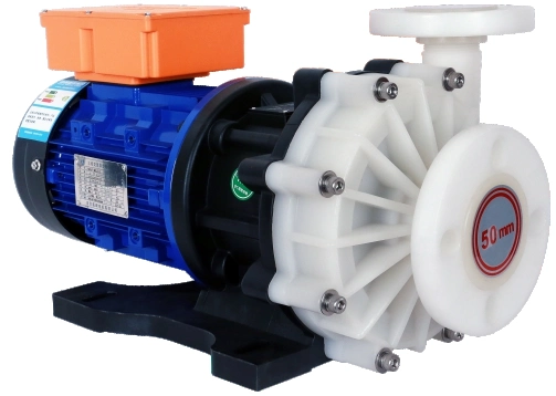
Measure Hydraulic Performance at the Installed Duty
After the pump starts reliably, measure the operating point. Record flow, suction and discharge pressure, tank level, liquid temperature, specific gravity when relevant, filter differential pressure, valve positions, motor current, and VFD frequency. Compare the measured result with the approved duty, not with a zero-head catalog flow.
If the installed flow is low, calculate the actual head before changing the pump. The QEEHUA guides to total dynamic head and pump curve versus system curve show why pipe losses, filter loading, static head, and valve position move the real operating point.
| Acceptance item | Record at start-up | Pass logic | Investigate if |
|---|---|---|---|
| Flow | Stable process flow at stated valve and VFD settings | Meets the agreed minimum and does not surge | Flow oscillates, drops as air releases, or misses the duty point |
| Pressure and head | Suction pressure, discharge pressure, tank level, liquid density | Calculated head agrees with the expected system condition | Pressure is high with low flow, or pressure cannot stabilize |
| Filter condition | Clean differential pressure and flow | Baseline is documented for later cartridge decisions | New cartridges show excessive differential pressure or bypass symptoms |
| Motor load | Current on each phase and VFD frequency | Current is balanced and remains within approved limits | One phase differs, current rises steadily, or overload protection trips |
| Mechanical condition | Noise, vibration, casing and bearing-area temperature | Readings stabilize without leakage or abnormal sound | Cavitation-like noise, rapid heating, rubbing, or pipe movement appears |
| Protection | Alarm and trip values, delays, reset and restart behavior | Each cause produces the specified safe state | A trip is bypassed, delayed without approval, or allows unsafe restart |
When a contract requires formal hydraulic performance acceptance, define the measurement method and tolerance in advance. ISO 9906:2012 covers hydraulic performance acceptance tests for rotodynamic pumps. Site measurements can still be useful for commissioning, but they should not be presented as an ISO-grade factory acceptance test unless the agreed instrumentation, test arrangement, and acceptance grade are met.
Stabilize the System and Create a Handover Baseline
Do not stop the test as soon as the first flow value looks correct. Run long enough for the line to vent, the bath temperature to approach its operating condition, and the filter pressure to stabilize. The required duration depends on the process and site procedure. Record values at consistent intervals so operators can see whether current, pressure, vibration, or temperature is drifting.
Commissioning also needs safe work control. Before maintenance, blockage removal, wiring changes, or coupling inspection, isolate hazardous energy and verify the safe state. The OSHA lockout/tagout standard and the UK HSE guidance on maintenance of work equipment both reinforce controlled isolation and competent maintenance practices. Apply the rules that govern the actual plant location.
The handover pack should include the final data sheet, pump curve, P&ID revision, material confirmation, instrument list, protection setpoints, measured baseline, unresolved punch items, spare-parts list, and operator response to each alarm. Photograph valve positions and instrument readings when site policy allows. A good baseline makes later troubleshooting faster because maintenance can compare today’s condition with the accepted start-up state.
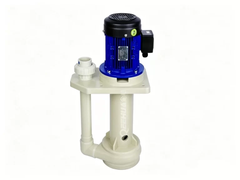
Hold Points That Stop Acceptance
Do not sign off the pump if rotation is wrong, the pump cannot stay filled, flow is unstable, the motor exceeds its approved load, a protection trip fails, the casing or piping leaks, vibration or temperature keeps rising, or the installed duty point falls outside the agreed operating range.
A failed commissioning point does not automatically mean the pump is undersized. The cause may be an air pocket, closed or mis-set valve, blocked strainer, undersized suction pipe, excessive filter pressure, wrong motor connection, incorrect instrument scaling, unsuitable control logic, or a changed chemical duty. Use evidence from the test before replacing equipment. QEEHUA’s guide to pump replacement versus system correction provides a structured decision path.
Need a commissioning data review? Send QEEHUA the pump model, bath chemistry, design flow and head, P&ID, measured pressures, motor current, tank level, filter differential pressure, and alarm setpoints. Email QEEHUA at info@qeehua.com for an application-focused check.
FAQ
Can I check pump rotation before filling a magnetic drive pump?
Do not assume that you can. Many magnetic drive and centrifugal pumps must not run dry, even for a short rotation check. Follow the exact model manual and site electrical procedure.
What readings should be recorded during chemical pump commissioning?
Record flow, suction and discharge pressure, tank level, liquid temperature, filter differential pressure, motor current by phase, VFD frequency, valve positions, noise, vibration, leakage, and every alarm or trip result.
How long should a PCB chemical pump commissioning test run?
Run long enough for air to clear and flow, pressure, current, vibration, and temperature to stabilize. The required duration depends on the bath, filter, operating temperature, and approved site procedure.
Should low-flow protection trip the pump immediately?
The delay must match the process and pump risk. It should reject harmless start-up transients but stop sustained no-flow or dry-running conditions before damage. Validate the delay during a controlled functional test.
What is the difference between commissioning and a factory pump test?
A factory test measures pump performance in a controlled test arrangement. Commissioning verifies the installed pump, piping, tank, filter, controls, safety functions, and process duty together at the plant.
Sources
External references used: ISO 9906:2012 hydraulic performance acceptance tests; OSHA control of hazardous energy; UK HSE maintenance of work equipment guidance.
Final Acceptance Note
A chemical pump is commissioned when the installed system proves application fit, safe start logic, stable hydraulic performance, and reliable protection鈥攏ot when the motor merely runs. Keep the measured baseline with the equipment record so future maintenance decisions can distinguish pump wear from system change.
