

Caustic Soda Pump Crystallization: Shutdown, Heating, and Safe Restart
A caustic-soda transfer pump that ran normally yesterday can appear seized, overloaded or unable to prime after a cold shutdown. The problem may not be the motor or the pump itself. Sodium hydroxide solution can form crystals or concentrated deposits when temperature and concentration fall outside the process window. A restriction can develop in a suction leg, foot valve, strainer, small bypass, pressure tap, valve cavity or the wet end. Starting the pump repeatedly against that condition can damage internals or create a hazardous release.
The correct response is to treat the line as a chemical and mechanical system. Identify the actual concentration, temperature history and location of the restriction. Isolate and depressurize it under the site procedure. Use the approved heating or dilution method. Then restart with a record of what changed. Do not assume that “warming the pump” alone is safe or sufficient, and do not put unapproved water into a line without considering heat of dilution, tank capacity and the required downstream concentration.
This guide is for plant teams and OEM buyers handling sodium hydroxide solutions in transfer, dosing, wastewater neutralization and chemical preparation systems. It focuses on field diagnosis and prevention. Material compatibility, concentration limits, heating design and safe-work requirements must be confirmed for the actual process.
What crystallization does to a caustic pump system
Sodium hydroxide is commonly supplied and used as an aqueous solution. Its physical behavior depends on concentration and temperature. A line that is acceptable during warm operation can become difficult to start after exposure to lower ambient temperature or a long idle period. Local QEEHUA application notes identify winter crystallization in caustic-transfer service as a recurring field issue. The notes are a practical warning, not a universal temperature chart. Confirm the liquid supplier’s concentration-temperature data for the actual solution.
Crystallization does not always look like a solid pipe. Deposits may form as a narrowed passage, a stiff valve seat, a packed strainer, an obstructed impulse line or a rough layer inside a pump cavity. The result can be low flow, high differential pressure, unstable current, loss of prime, leakage at a forced joint or a pump that trips before liquid reaches the discharge point.
Why repeated starts make the situation worse
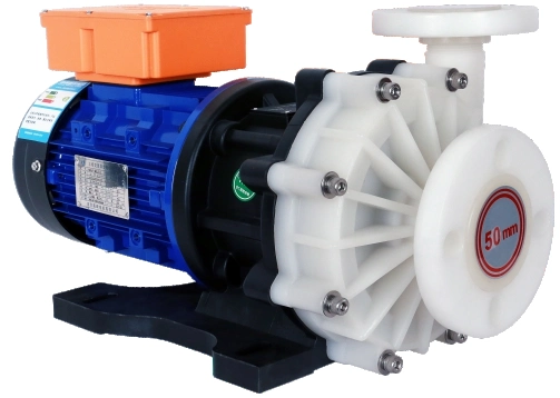
A centrifugal or magnetic drive pump needs an open liquid path and suitable internal circulation. A blocked suction can cause dry running or cavitation. A blocked discharge can move the pump into a low-flow heating condition. Crystals or deposits inside the wet end can increase friction and jam internal components. A magnetic drive unit may lose synchronism if internal drag or hydraulic demand exceeds its coupling capacity. The article on magnet decoupling explains why repeated electrical resets are not a safe diagnostic method.
Do not use a higher overload setting to force a start. The overload is an alarm that needs a process explanation. A successful forced start can break a deposit loose, but it can also move solids into a valve, filter or pump bearing area. It may leave an operator standing beside a hot, pressurized caustic line when a joint leaks.
Find where the restriction formed before opening equipment
Start with history. Note the caustic concentration, supplier batch, tank level, last transfer, outdoor temperature, line or tank temperature, idle time and any heat-tracing alarm. Ask whether the restriction appeared after a weekend, a delivery, a dilution operation, filter maintenance or a control change. The time sequence often distinguishes a cold-shutdown problem from a sudden mechanical failure.
Read pressure and temperature as a pair
Compare suction pressure or level, discharge pressure and available temperature readings. A high discharge pressure with little flow may point downstream. A low suction reading, collapsed flexible hose or loss of prime may point upstream. A reading from one gauge is not proof by itself because a small pressure tap can crystallize too. Check whether the gauge connection is warm and clear before trusting the display.
Use a documented, safe inspection route. External pipe temperature can identify a cold section, but it does not show whether the bore is clear. Do not strike, drill or remove a fitting from a pressurized caustic line. Do not rely on a hand test near a line that may be hot. Use the plant’s approved instruments and protective equipment.
Work from the tank outward or from the receiving point backward, but keep the route consistent. Mark every temperature point and every place where liquid can remain after the transfer stops. A line with heat tracing on the main run may still have an untraced branch at the pump suction, a filter housing exposed to air, or a short section behind an insulation termination. If the same location fails after each cold event, the system has a repeatable thermal weak point. Photograph it and add it to the piping isometric instead of treating the failure as an operator error.
Use the condition of the liquid to rank causes. A clear liquid path with a pump that will not rotate can indicate internal mechanical damage, while a line that warms slowly with a pressure change but no flow suggests a restriction. A strainer that shows a sudden pressure drop after warming may release deposit material downstream. Plan for that possibility. A controlled drain, filter inspection and chemical-compatible flush route can prevent a partially dissolved deposit from becoming a second blockage at the pump or control valve.
Check small passages as well as main pipe
Small bypasses, drain legs, instrument connections, check-valve cavities and strainers are often the first places to hold stagnant liquid. A large pipe can look normal while a small minimum-flow return or pressure-sensing line is restricted. Mark these dead legs on the piping sketch. Include them in heating, flushing and maintenance procedures rather than treating them as incidental accessories.
| Observed condition | Checks before opening | Likely area to investigate | Unsafe shortcut to avoid |
|---|---|---|---|
| Motor trips immediately after a cold shutdown | Liquid temperature, valve position, pump freedom under approved procedure | Wet end, suction strainer or discharge blockage | Increasing overload setting or repeated starts |
| Low flow and low suction indication | Tank level, suction valve, venting, strainer and hose condition | Suction leg, foot valve or restricted strainer | Assuming the tank is empty without checking |
| High discharge pressure with low flow | Valve alignment, downstream temperature and filter condition | Discharge pipe, control valve or small bypass | Opening a hot or pressurized joint |
| Instrument readings disagree | Impulse-line temperature and isolation arrangement | Pressure tap or blocked sensing line | Changing the control setpoint without verification |
Shutdown and isolation before heating or flushing
Caustic soda is corrosive. The U.S. National Institute for Occupational Safety and Health lists sodium hydroxide as a substance that can cause severe burns and eye damage; its pocket guide entry is a concise reference for the hazard. The site-specific safety data sheet, chemical concentration, temperature and equipment design govern the actual precautions.
Before heating, flushing or opening the system, stop the pump, isolate electrical energy, close and secure relevant valves, depressurize, drain to the approved containment point and verify the condition. Follow the site’s hazardous-energy procedure. OSHA’s lockout/tagout rule provides the general principle for energy isolation. The chemical procedure must also address residual caustic, thermal expansion and emergency wash facilities.
Do not improvise dilution
Adding water to sodium hydroxide can release heat. The result depends on concentration, quantity, mixing, vessel condition and where the water contacts the caustic. An unplanned water injection can create hot liquid, splashing, a concentration change or a tank overflow. Only use the approved dilution sequence, designated connection and mixing procedure. If the process needs a final concentration, arrange for sampling and verification before returning product to service.
Confirm material and temperature limits
Heating a blocked line may be part of the approved design, but every component has a temperature limit. Check pump casing material, gaskets, valves, hoses, instruments, plastic pipe supports and insulation. A heat source that solves a crystal problem can damage a fluoroplastic component, soften plastic piping or create a hot spot if it is applied without control. The QEEHUA guide on PPH, PVDF and fluorine-lined magnetic pump materials can support the materials discussion, but the model drawing and chemical data remain the final source.
Heating and dilution decisions should follow the process design
There is no one “safe temperature” to publish for every caustic solution. Concentration, desired product condition, insulation, ambient exposure and equipment limits all matter. Use the chemical supplier’s concentration-temperature chart and the site’s documented setpoints. The field task is to warm the identified cold section uniformly enough to restore a controlled liquid path, not to overheat the nearest accessible component.
Heat tracing and insulation need an inspection plan
Heat tracing can prevent a shutdown problem when it is correctly designed, powered and monitored. It can also fail quietly through a tripped circuit, damaged insulation, wet junction box, failed sensor or a setpoint that no longer matches the solution concentration. Include tracing circuits and temperature sensors in the preventive-maintenance route. Record the expected line temperature at defined points, then investigate deviations before a long shutdown.
Insulation reduces heat loss but does not correct a missing heat source. Inspect for gaps around valves, flanges, strainers and support shoes. Those discontinuities are often where deposits start. A maintenance plan should identify which insulation can be removed for inspection and how it will be restored after valve or pump work.
Commission a new tracing system with a simple cold-condition test. Verify each circuit energizes, the displayed temperature matches an independent measurement, alarms are received where operators can act, and the system reaches the intended condition without overheating nearby plastic or instrument components. Repeat the check after electrical work, insulation repair or a process concentration change. A trace circuit can be electrically healthy but still provide inadequate heat because the sensor location, insulation or contact with the pipe has changed.
Where redundancy is important, identify the consequence of one lost trace circuit. The response may be a controlled drain, recirculation to a tank, reduced concentration, production hold or a shift inspection. The response should be written before winter or before the first cold outage. Waiting for crystallization to decide who is allowed to operate a heat source leads to rushed work around corrosive liquid.
Use flushing only when the system is designed for it
A flushing connection can make recovery easier, but it needs a destination, flow path, isolation logic and chemistry plan. The flush medium must be compatible with the process, waste-treatment capacity and next batch. Confirm whether the pump can circulate the medium safely, whether the system must be drained first and whether a check valve can trap liquid in a branch. A temporary hose connected to an unverified port is not a flushing procedure.
Controlled restart after the liquid path is restored
Restart only after the line has been inspected, warmed or flushed under the approved method, and returned to its intended concentration and temperature condition. Confirm the tank level, suction valve, discharge path, pump priming requirement, vent condition, filter or strainer status and all temporary connections removed. For a magnetic drive pump, check that the event did not leave signs of overheating or internal damage before starting.
Caustic-pump restart record
- Record concentration, temperature, tank level, idle time and the location of the restriction found.
- Confirm energy isolation has been removed only after all guards, connections and valves are restored.
- Verify the suction source is available and the pump is filled or primed as required by its design.
- Start at the approved speed and watch current, pressure, flow and visible leakage.
- Check the bypass, filters, small instrument lines and heat-traced sections during the first stable run.
- Take a sample or process measurement when concentration control is part of the service.
- Update the shutdown procedure if the restriction showed a design or maintenance gap.
Look for a second restriction
A pump can restart after the main line is cleared while a smaller branch remains partly restricted. Watch flow, pressure and temperature through the full process cycle. Check filter differential pressure and any minimum-flow return. A second problem may emerge when the line reaches normal pressure or when a control valve moves. Record the first hour of operation so the next shutdown is based on evidence.
Design and prevention checks for cold caustic service
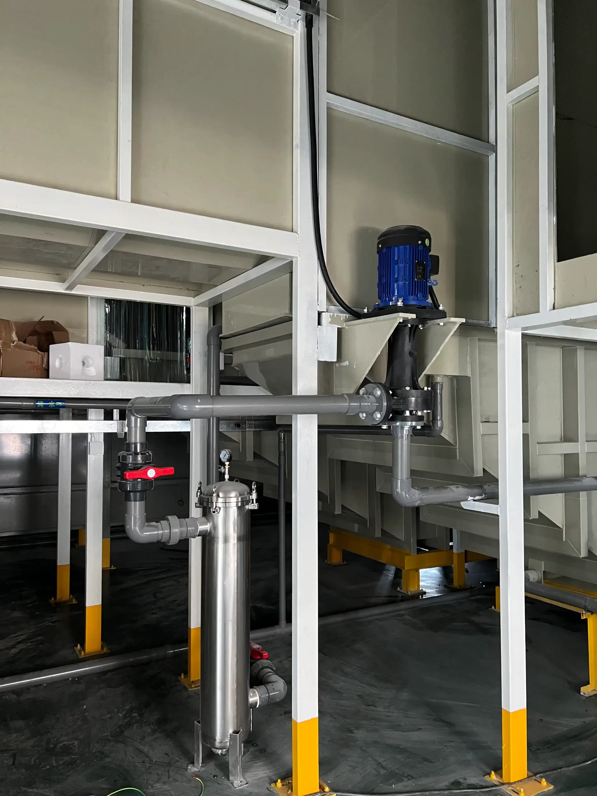
Preventing crystallization begins with the concentration-temperature envelope. Get it from the liquid supplier and put the applicable limits in the operating procedure. Design the tank, line, valves, filters and instrument legs around that envelope. Avoid dead legs where practical. Provide drainability, appropriate slope, insulation and approved heat tracing where the process requires them. Make sure a power failure or weekend shutdown has a defined response.
Review the storage and transfer sequence too. A delivery may arrive at a different concentration or temperature from the normal tank contents. A mixing step may change the local concentration in a low point before the whole tank is uniform. A line that is safe for one product grade may not remain safe for another. Put the received concentration, temperature and any blending instruction on the shift record when they affect the protected temperature range. This gives the next operator a usable reason for a tracing alarm or a cautious restart.
Review the whole route, not only the pump
Follow the caustic route from storage tank to injection point or process vessel. Note outdoor sections, unheated rooms, low points, small-bore branches, spare connections, strainers, bypasses and flowmeters. The QEEHUA article on plastic pipe head loss is relevant here because a small added restriction can change the pump’s duty; for cold caustic, it may also be the place where stagnant solution needs attention.
Make the shutdown sequence specific
Write whether the system remains heated, recirculates, drains, flushes or is placed in a protected standby state. Identify who checks the trace circuit and who verifies temperature after a power event. A generic instruction to “keep warm” does not specify the action, setpoint, alarm or responsible person. A short, location-specific checklist is more reliable during a late shift or a restart after a weekend.
Set the inspection frequency from the actual risk. A short indoor transfer line that is emptied after use needs a different routine from an outdoor bulk-storage line that remains full through the night. Review the first cold-season events and adjust the procedure with evidence: recorded temperature, concentration, location of deposits, trace status and actual downtime. This turns a recurring cold-start problem into a maintenance item with a measurable outcome.
Include pump selection in the review. Confirm material compatibility, allowable liquid temperature, seal or magnetic-drive configuration, internal-flow requirement and the need for a bypass. The existing QEEHUA sodium-hydroxide pump selection article covers the selection context. This article complements it by addressing what happens when the process condition changes after shutdown.
Record the verified return temperature before normal production resumes.
For a caustic-soda transfer or dosing review, send QEEHUA the sodium-hydroxide concentration, temperature range, expected shutdown duration, pipe route, heating or insulation details, pump model and flow requirement at info@qeehua.com. We can help identify the selection and piping information needed to prevent repeat cold-start restrictions.
FAQ
Why will a caustic-soda pump not start after a cold shutdown?
A cold condition can create crystals or concentrated deposits in the suction line, strainer, valve, bypass, instrument connection or pump wet end. Confirm the actual concentration, temperature history and restriction location before restarting.
Can I add water to dissolve caustic-soda crystals in a pump line?
Only use a documented and approved dilution or flushing procedure. Adding water to sodium hydroxide can release heat and change concentration, so the connection, mixing, containment and downstream process must be controlled.
Should caustic transfer lines be heat traced?
Heat tracing may be appropriate when the solution concentration, temperature range and ambient conditions require it. The design must follow supplier data and equipment temperature limits, with inspection of tracing, sensors and insulation.
Can a blocked caustic line damage a magnetic drive pump?
Yes. A restriction can cause dry running, low-flow heating, internal drag or high torque demand. Stop the pump, isolate it safely and inspect the system rather than repeatedly resetting the drive.
What should be recorded after a caustic-pump cold-start event?
Record concentration, temperature, idle time, affected location, heating or flushing action, pump current, pressure, flow and any changes to the shutdown procedure.
