

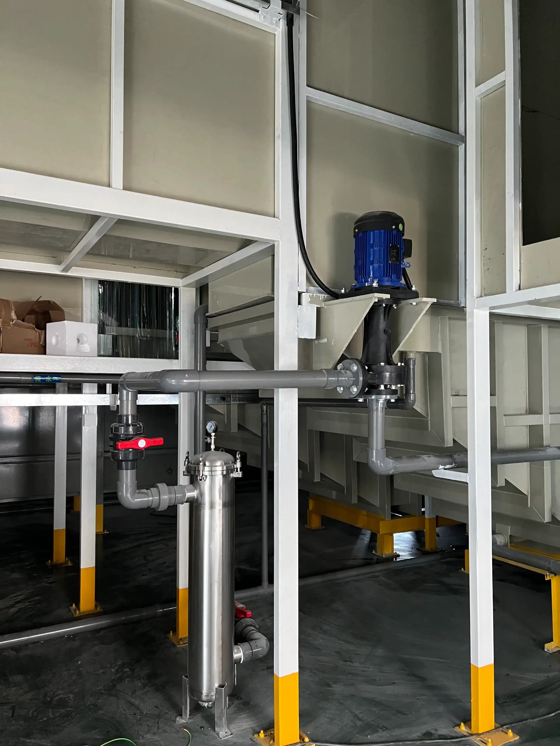
Parallel Chemical Pumps: Flow Balancing and Check-Valve Logic
Two chemical pumps installed in parallel do not automatically deliver twice the flow. Their combined output is set by the pump curves and the system curve that the shared pipework creates. If one pump has a different curve, a partly closed valve, a blocked filter, a weak check valve or a different VFD speed, it may carry much less flow than expected. In a worse case, one running pump can push liquid backward through the idle branch.
Parallel arrangements are useful when a process needs capacity in stages, standby duty, lower-flow operation with one pump, or continuity during maintenance. They are common on wet scrubber recirculation, plating circulation, wastewater transfer and chemical skids with several operating modes. They also demand more thought than a single-pump line. The piping, check valves, controls and commissioning test must prove that each pump can start, stop and share duty without backflow, overheating or a surprise shift in the operating point.
This article explains the system behavior behind a parallel chemical-pump installation. It is not a generic “two pumps are better” guide. The aim is to help an OEM or plant team ask the questions that determine whether the second pump provides usable capacity or creates a difficult troubleshooting problem.
When parallel pumps are a good fit
Choose parallel pumps when the required flow has meaningful operating steps. A scrubber may need one pump in normal operation and a second pump during peak exhaust load. A plating line may need a low circulation rate during idle periods and higher turnover during production. A transfer system may need a duty pump plus standby pump so maintenance does not stop the process. In those cases, two smaller pumps can give better control and availability than one oversized pump throttled at low demand.
Parallel duty is not always the answer. If the process needs a single fixed flow with no redundancy requirement, a correctly selected single pump can be simpler. If the system has very high static head and little friction change, adding a second identical pump may produce less additional flow than expected. If the liquid contains solids that routinely foul branch strainers or check valves, the maintenance plan may outweigh the theoretical benefit. Start with the process modes, not the number of pumps available in the catalogue.
Define the duty cases before choosing the pumps
List the cases that the installation must handle: one pump operating, both pumps operating, one pump unavailable, low-speed circulation, maximum-speed circulation, dirty filter, minimum tank level and the expected liquid temperature range. For each case, state the required flow, total head, liquid density and the permitted operating time. The local QEEHUA electroplating and PCB application notes include examples of parallel-pump interference where systems were selected for nominal capacity but had no clear one-pump and two-pump acceptance points.
These cases become the curve review and PLC sequence. They also prevent an all-too-common argument during commissioning: one team expects two pumps to double flow, while another team sees a lower combined flow and assumes one pump is defective. The answer is usually in the system resistance and branch conditions.
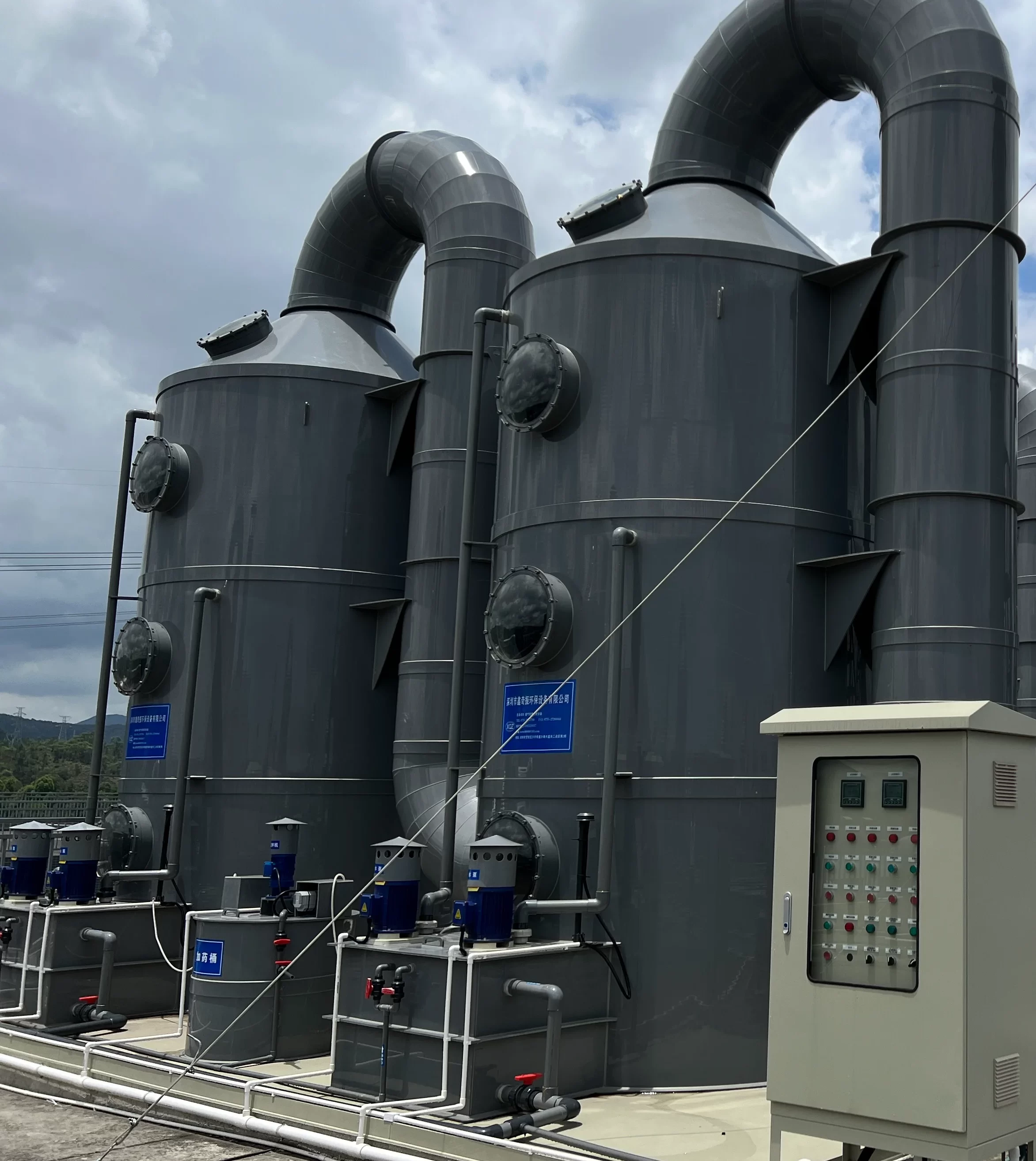
How parallel-pump curves combine with the system curve
At a given head, the flows from parallel pumps add. For identical pumps operating at the same speed, the combined curve is built by adding each pump’s flow at the same head. If one pump delivers 10 m3/h at 20 m head, two identical pumps can supply about 20 m3/h at that same 20 m head. The operating point, however, is where the combined pump curve meets the actual system curve. It may not be 20 m head.
A system curve can be represented in a simple form as:
Hsystem = Hstatic + K x Q2
Hstatic is the elevation or fixed pressure component. K x Q2 represents friction losses in pipe, fittings, valves, filters and equipment. As total flow rises, friction rises approximately with the square of flow in a suitable turbulent-flow range.
When the second pump starts, total flow rises, and friction loss rises with it. The combined operating point therefore moves along the system curve. The combined flow is usually less than exactly twice the one-pump flow. The U.S. Department of Energy’s mechanical-science handbook describes the same parallel-pump principle: at the same head, flows add, but the final flow is governed by the system curve.
A short curve example
Suppose one pump operates at 12 m3/h and 24 m head on the existing line. The operator adds an identical second pump and expects 24 m3/h. The shared discharge header and spray nozzles now see more flow. Their friction loss rises. The new operating point may be 20 m3/h at 28 m head, not 24 m3/h at 24 m. That can be a successful result if the 20 m3/h meets the peak process demand. It is a problem only when the design assumed a flow that the system cannot accept.
Plot or request the curves rather than relying on the example. Include the suction and discharge branch losses for each pump, common header losses, filters, valves, nozzles and any back-pressure device. The existing QEEHUA guide on pipe head loss in plastic chemical lines helps turn those fittings into an explicit system calculation.
Static head changes the result
In a circuit with a large static lift, the system curve begins at a higher head. Adding a second pump may increase flow modestly until the combined curve provides enough head above that static requirement. In a recirculation loop with very little static head, friction dominates and the second pump can create a larger flow increase. Neither situation is universally better. It tells the designer which curve and control checks matter.
Why matching pumps, speed and branch losses matters
Identical model numbers do not guarantee identical field behavior. One branch can have a longer suction pipe, a dirtier strainer, a partially closed isolation valve, a different check-valve spring, an air pocket or a VFD setpoint that differs by a few hertz. The pump with lower branch resistance may take more of the shared flow. The other may operate at a low-flow point where heat, vibration or poor internal circulation becomes a risk.
Use compatible curves, not a casual mix of pumps
Parallel pumps should have compatible head-flow curves in the duty range. A large and a small pump can run in parallel only when the curve and control study shows stable operation. Otherwise the larger pump can force the smaller pump toward shutoff or reverse flow. For chemical service, also match wetted materials, temperature limits and the required solids tolerance. A spare that is mechanically similar but has a different impeller diameter or magnetic coupling limit may not be an interchangeable standby.
For variable-speed operation, make the speed relationship explicit. Two identical pumps running at the same frequency are the simplest arrangement. If one pump stages on at a lower starting speed, define the ramp, the pressure or flow condition for release, and the maximum permitted speed. A faster pump does not simply “help more”; it can alter the operating point of both branches.
Keep each suction branch credible
Parallel pumps may share a suction header or draw from the same tank. Check that both branches have adequate submergence, venting and suction loss at the two-pump flow. A suction header sized for one pump can become the limiting restriction when both run. An unequal branch may draw air or cavitate first. If a common strainer is used, its pressure drop at the combined flow must be included in the two-pump case.
Use the same discipline for strainers and filters on individual branches. A clean branch and a fouled branch are not balanced branches. Fit differential-pressure indication where operators can act on it, and put cleaning instructions in the routine maintenance plan. The local application material notes that poor filter control can cause unstable circulation and PCB-process quality problems; parallel duty makes that imbalance harder to spot without measurements.
Check-valve and isolation-valve logic for shared discharge headers
Each pump discharge branch normally needs an isolation valve and a check valve before it joins the common header. Their jobs are different. The isolation valve allows maintenance and controlled testing. The check valve limits reverse flow when a pump is stopped, trips or is removed from service. A check valve is not a substitute for an isolation procedure, and an isolation valve is not a reliable automatic backflow device.
Place the check valve where it can do its job
Locate the check valve in the individual discharge branch before the common header, in the arrangement approved by the pump and piping design. Keep it accessible for inspection. A valve buried behind pipework without a service spool often remains in place until it fails. Select the construction for the chemical, temperature, pressure, orientation and expected flow. A spring-loaded valve, swing check or other design has different cracking pressure and dynamic behavior. The selection must be based on the actual circuit, not a generic preference.
A valve that leaks backward can make a stopped pump spin in reverse, fill the idle branch, or make it impossible to isolate a pump safely. A valve that has excessive cracking pressure adds branch loss and can distort flow sharing. A valve that chatters at low flow can wear rapidly. During commissioning, test both pumps off, each pump on alone and both pumps running. Watch branch pressure or flow if instrumentation is available.
Do not force a closed valve as a balancing method
A partly closed manual valve can be used temporarily for an approved test, but it is a poor long-term fix for an unequal pump system. It adds variable loss, creates an easy-to-change field setting and may push a pump toward low flow. Correct the source: wrong pump curve, branch piping difference, fouled filter, faulty check valve, VFD setpoint or inaccurate instrument. If permanent balancing is required, design it and document the setting with a clear process reason.
| Component | Primary job | Common failure effect | Commissioning check |
|---|---|---|---|
| Individual isolation valve | Safely remove or test one pump | Cannot isolate a pump or valve setting restricts branch flow | Confirm open position for service and lock/tag position where required |
| Individual check valve | Limit reverse flow from common header | Reverse rotation, backflow or branch pressure loss | Run one pump with the other stopped and observe the idle branch |
| Branch strainer/filter | Protect pump or process from contamination | Unequal branch loss and low-flow operation | Record clean and maintenance differential pressure |
| Common header | Carry total pump flow | Unexpected friction loss at two-pump duty | Compare pressure/flow against the two-pump curve calculation |
Control sequence, staging and minimum-flow protection
The control sequence should explain what happens at startup, normal operation, peak demand, fault, and shutdown. A simple lead-lag arrangement alternates the lead pump on a schedule so run hours are shared. The lag pump starts when flow, pressure, level or process demand crosses a defined condition. The lag pump stops with a separate condition and delay so it does not hunt on and off every few minutes.
Use a process signal that represents the real need
Pressure is often convenient, but it may not prove that all branches receive adequate flow. Flow is direct but can be more complex to install. Tank level may suit a transfer system. Choose the staging signal based on what the process is protecting. A scrubber recirculation system might use header pressure plus a low-flow trip. A transfer system might use receiving-tank level plus a maximum-pressure limit. An electroplating loop might use VFD speed and filter condition alongside the circulation requirement.
Document sensor failure behavior. A failed pressure transmitter should not make both pumps run at maximum speed without another limit. A blocked impulse line can show a stable pressure while flow has fallen. The QEEHUA article on level, flow, pressure and VFD interlocks gives a broader way to combine these signals.
Protect each pump at low flow
When one pump is stopped, the running pump may move to a different point on its curve. When two pumps run at low system demand, each pump can see a lower individual flow. Check minimum continuous stable flow and any internal-cooling requirement in the pump documentation. A minimum-flow bypass can protect a centrifugal chemical pump when the process cannot accept that flow. The QEEHUA guide to minimum-flow bypass design explains why the return route and heat balance must be considered, not only the bypass valve size.
Fault handling should isolate the problem branch
Define the response when one pump trips. The standby or lag pump may need to start, but only after verifying that the common cause is not an empty tank, closed suction valve or dry system. A faulted pump should be prevented from repeated automatic restarts if there is evidence of a mechanical issue, dry running or magnetic-coupling problem. Record the alarm order so maintenance can distinguish a genuine pump fault from a shared suction or header event.
Commissioning tests and records
Commissioning should prove one-pump and two-pump operation separately. Begin with clean strainers or filters, known valve positions and a defined liquid condition. Record suction level, VFD frequency, motor current, discharge pressure, branch pressure if available, total flow and visible leakage. Then test the sequence in the same order that the process will use.
Parallel-pump field test sequence
- Run Pump A alone and record flow, head or pressure, current and vibration observation.
- Stop Pump A and confirm its check valve prevents reverse flow from the header.
- Run Pump B alone and repeat the measurements.
- Run both pumps at the approved speed. Compare total flow with the curve calculation and check individual branch behavior.
- Stage one pump off and on using the normal control signal. Check for pressure surge, check-valve chatter and unstable hunting.
- Repeat the test at the highest approved demand and with the planned low-demand control mode.
- Record alarm and failover behavior with the site safety procedure in force.
Do not judge success by total flow alone. A combined flow number can look correct while one pump is overloaded and the other carries little flow. Compare current, pressure and temperature where possible. Confirm that valves are accessible, labels are correct and operators understand which valves must remain open during normal duty.
Pay attention to the first ten to thirty seconds after the second pump starts. A brief pressure movement is normal in many systems. Persistent oscillation, repeated check-valve noise, a fast current rise in one motor or a branch that remains cold are not. Capture the trend rather than trying to interpret the sound from memory. The same short record can reveal a lag-pump ramp set too high, a closed branch valve, a blocked strainer or a transmitter that is controlling the wrong part of the circuit.
For skid acceptance, include the parallel operation cases in the test record. The QEEHUA factory acceptance test checklist can provide the structure, but the site piping and actual liquid condition still need a final commissioning check after installation.
Planning a duty/standby or staged-flow chemical-pump package? Send QEEHUA the required flow for one-pump and two-pump operation, liquid data, piping sketch, common-header details, valve list and control sequence at info@qeehua.com. We can help review pump-curve compatibility, branch losses, check-valve placement and the commissioning points that should be written into the project record.
FAQ
Do two parallel chemical pumps always double the flow?
No. At a given head their flows add, but the final combined flow is set by the system curve. Shared-pipe and equipment friction usually rise as total flow increases.
Does each parallel pump need a check valve?
Each discharge branch normally needs a suitable check valve before the common header to limit reverse flow through a stopped pump. The exact arrangement must follow the pump and piping design.
Can different pump models operate in parallel?
They can only be used when their curves, controls, material limits and branch losses are reviewed for stable operation. A larger pump can otherwise dominate flow or force the smaller pump toward an unsuitable point.
Why is one parallel pump drawing more current than the other?
Possible causes include unequal branch resistance, different VFD speeds, a fouled strainer, valve position, check-valve behavior, different impeller curves or a suction problem. Compare branch and process data before changing a motor setting.
What should start the lag pump?
Use a documented process signal that represents demand, such as flow, pressure, level or a defined production mode. Include delays and fail-safe behavior so the pumps do not hunt or start on an unsafe empty system.
