


For most PCB wet process chemical pump lines, place the flowmeter on the discharge side. The pipe should stay full, the flow should be stable, and the meter should have the straight-run and orientation required by its manufacturer. Avoid using a flowmeter as a restriction on the pump suction line. Do that only after the meter supplier and pump engineer check NPSH, chemical compatibility, pressure loss, and maintenance access. The goal is not just to show a number. The goal is to give operators a flow reading they can trust when filtration, spray pressure, dosing balance, or pump protection depends on it.
OEM skid builders and maintenance teams often add a flowmeter late, after the pump, filter, valves, and tank layout have already taken the easy pipe space. That late decision is where many bad readings begin. A meter installed after a sharp elbow, in a partly filled down pipe, beside a throttling valve, or upstream of a pump may still display flow. It may not represent the real circulation rate through the bath.
Why placement matters more than the meter brand
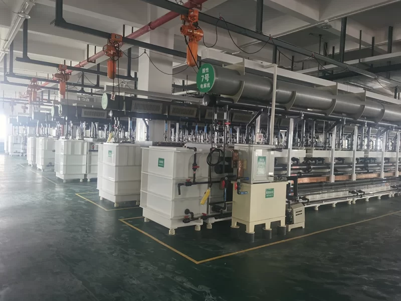
A PCB wet process line may use magnetic drive pumps, vertical pumps, chemical filters, spray headers, bypass valves, pressure gauges, and level interlocks in one compact skid. QEEHUA local application files identify PCB, electroplating, coating, wastewater treatment, and scrubber systems as common use cases. These lines often combine chemical pumps, vertical pumps, filters, flowmeters, pressure gauges, valves, and corrosion-resistant piping. The same local pain-point files also flag unstable flow, blocked filters, air pockets, wrong pump-to-filter matching, and uncalibrated gauges as recurring field problems.
That means a flowmeter is part of the troubleshooting system. It helps a team locate low flow. The cause may be the pump, a clogged filter cartridge, a suction leak, a closed valve, gas binding, or a wrong pump operating point. If the meter location is wrong, the team may replace a healthy pump or ignore a real process fault.
This is different from calculating the required circulation rate. For design flow sizing, use a separate engineering pass such as a PCB wet process pump flow rate calculation. Flowmeter placement comes after that. It asks where the measured value will reflect the duty that matters: total circulation, filter loop flow, spray header feed, wastewater transfer, or batch tank turnover.
The practical default: discharge line, full pipe, stable flow
The safest default for many centrifugal and magnetic drive chemical pump loops is a discharge-side flowmeter. Install it in a pipe section that stays full under normal and low-flow operation. The meter should sit far enough from elbows, reducers, valves, pumps, and tees to meet the manufacturer instructions. Emerson’s magnetic flowmeter installation guidance describes the common 5 pipe diameters upstream and 2 pipe diameters downstream reference for magnetic meters. It also explains why disturbed velocity profiles can shift accuracy. Endress+Hauser’s Promag instructions caution against installing a magnetic flow sensor on the intake side of a pump. The same instructions state that correct measurement requires a completely full measuring tube.
Do not treat those values as a universal rule for every meter. Paddle wheel, turbine, vortex, ultrasonic, Coriolis, and magnetic flowmeters do not share the same straight-run, conductivity, pressure-drop, solids, and chemical-resistance limits. The RFQ should name the meter type and ask the supplier to confirm the required straight pipe, orientation, wetted materials, gaskets, electrode materials, pressure rating, and signal output.
| Installation question | Why it matters in PCB or plating lines | Practical specification note |
|---|---|---|
| Will the pipe stay full at low flow? | Air bubbles or partial filling can make a magnetic meter read erratically or falsely. | Use a low-point or rising vertical section when needed. Avoid high points and free outlets. |
| Is the meter on suction or discharge? | Suction-side restrictions can worsen air entry, cavitation risk, and NPSH margin. | Prefer discharge-side placement unless an engineer approves the suction design. |
| What is upstream of the meter? | Elbows, reducers, valves, and pumps disturb the flow profile. | Reserve straight pipe according to the meter manual. Do not guess from another meter type. |
| What chemical contacts the meter? | Acid, alkali, oxidizers, chloride, temperature, and solids affect liners, electrodes, seals, and bodies. | Confirm PVDF, PTFE/FEP/PFA, PP, stainless steel, EPDM, FKM, or other wetted parts case by case. |
| What signal will the PLC use? | A display-only meter may not help with alarms, VFD control, or interlocks. | Specify 4-20 mA, pulse, relay, RS485, or other output before panel design. |
Where readings fail in PCB wet process loops
On the suction side of a magnetic drive pump
A suction-side meter may look convenient because the pipe is near the tank. It can still be the wrong choice. Any extra pressure loss, pocket, gasket intrusion, or fouling point on the suction line can make the pump harder to feed. For PCB etching, developing, stripping, and plating baths, local field notes already show that small suction errors can create air pockets, unstable flow, cavitation symptoms, and dry-running risk. When suction behavior is the concern, read the flowmeter together with the suction layout, foot valve, tank level, and chemical pump foot valve condition.
Immediately after a pump outlet elbow or throttling valve
A compact skid may put the meter right after the pump discharge, a 90-degree elbow, or a control valve. The reading may be repeatable but offset. That is risky when the team uses the number for acceptance testing, filter-change triggers, or low-flow shutdown. Siemens magnetic flowmeter instructions state that accurate flow measurement needs straight inlet and outlet lengths and distance from pumps and valves. They also advise U-tube placement for partially filled or downward-flow pipes with free outlet.
In a filter bypass or shared return line
If the meter sits in the wrong branch, it may show pump circulation but not filter flow. This matters after cartridge changes, when operators may open a bypass for maintenance and forget that the display no longer represents the filtered path. If the line includes a bypass, use the meter tag name to state exactly what it measures. Examples include pump discharge total flow, filter inlet flow, filtered return flow, or spray-header flow. This also keeps it separate from a chemical filter bypass loop decision.
In gas-release or crystallizing service
Developer, stripping, oxidizing, hot, or crystallizing liquids can release gas, coat electrodes, clog small passages, or foul mechanical meter parts. A number on the display may drift before the pump actually fails. In these lines, combine the flow reading with pressure, filter differential pressure, tank level, and visual checks. QEEHUA’s product knowledge notes PVDF and fluoroplastic options for strong acid or crystallizing duties. Local pain-point records also call for temperature control, draining stagnant pump cavities, and cleaning lines where crystallization is expected.
What to specify before the skid is built
A good RFQ does not simply say, “add one flowmeter.” It tells the skid builder what decision the meter must support. If the decision is filter cartridge replacement, the meter belongs near the filter path. If the decision is spray-header uniformity, it may need to measure the header feed. If the decision is pump protection, the meter may feed the same logic family as level, pressure, current, and VFD status. For broader control logic, link this topic to the existing PCB pump interlock logic instead of making the flowmeter carry every protection task by itself.
- Define the measured duty: total pump flow, filter flow, spray flow, transfer flow, dosing dilution flow, or wastewater line flow.
- List liquid name, concentration, temperature, solids, gas release, conductivity, viscosity, specific gravity, and cleaning method.
- Reserve pipe space for the chosen meter type before valve and skid dimensions are frozen.
- State whether the meter is for local display, PLC trend, low-flow alarm, batch totalization, or acceptance testing.
- Confirm wetted materials, liner, electrodes, seals, grounding, cable protection, and enclosure rating for acid mist or splash zones.
- Ask for a calibration or verification method that maintenance can repeat without stopping the whole wet process line.
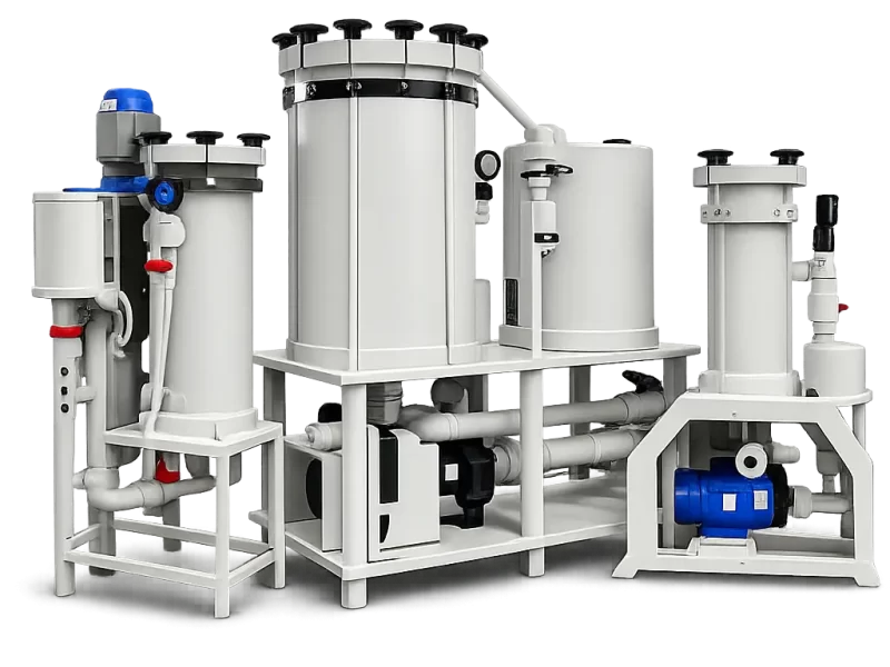
QEEHUA can review pump, filter, piping, and instrumentation requirements together when an OEM needs one consistent wet-process package. For pump-side hardware, keep the product link focused. QEEHUA’s pump protection device is relevant when dry-run, overload, and phase-loss protection must be coordinated with the pump package. The flowmeter specification still needs its own process and installation checks.
Commissioning checks that catch bad readings early
Commissioning is the right time to prove that the meter reading makes sense. Start with the pump running near the expected duty point, the suction line full, the filter vented, and the valves in their normal positions. Compare the flow display with discharge pressure, filter pressure, tank return behavior, and the pump curve. If the meter shows normal flow while the spray header is weak, the meter may be in the wrong branch. The same risk applies when filter pressure is abnormal but flow looks acceptable.
Use a short acceptance sheet. Record pump model, impeller or motor configuration, liquid temperature, valve position, filter cartridge condition, suction level, pressure readings, flow reading, and VFD frequency if used. If the operating point does not match the expected duty, verify the pump curve versus system curve before changing the meter range or blaming the pump.
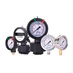
Maintenance teams should also treat zero flow, low flow, and unstable flow as different alarms. Zero flow may mean closed valve, empty tank, failed pump, lost prime, or meter fault. Low flow may mean filter plugging, impeller wear, suction restriction, or wrong VFD speed. Unstable flow may point to gas release, air pockets, vortexing, pressure-gauge diaphragm clogging, or poor meter location. When pressure values look suspicious, use the existing guide on chemical filter pressure gauge problems to avoid chasing a false trend.
FAQ
Should a flowmeter be installed before or after a chemical pump?
For most centrifugal and magnetic drive chemical pump loops, install the flowmeter after the pump in a full, stable discharge pipe section. Avoid suction-side installation unless the team has checked meter pressure loss, suction conditions, and pump NPSH margin.
Can one flowmeter prove both pump flow and filter flow?
Only if the piping has no bypass or branch that separates pump discharge flow from filtered return flow. If a bypass, drain, or shared return exists, label the meter by the exact branch it measures.
Why does a magnetic flowmeter need the pipe to stay full?
A magnetic flowmeter calculates flow from conductive liquid moving through the measuring tube. Air pockets, partial filling, or gas release can interrupt the signal and make the displayed value unreliable.
What should an OEM include in a pump skid RFQ when a flowmeter is required?
Include liquid chemistry, temperature, solids, flow range, pipe size, meter purpose, signal output, wetted materials, required straight pipe, and enclosure rating. Also state whether the value controls alarms, VFD speed, or acceptance testing.
For an OEM or maintenance review of pump, filter, instrument, and control layout, send the duty point, liquid data, pipe sketch, and target flow range to info@qeehua.com.
A location check before the flowmeter becomes the control point
A flowmeter on a PCB wet-process line should not be treated as a loose accessory. It becomes part of the control loop. If the meter reads low because of bubbles, an elbow, a partly full pipe, or a valve too close to the sensor, the pump may be blamed for a process problem it did not cause.
Start with a simple velocity check: v = Q / A. This follows the basic flow relationship used in flow measurement references such as Endress+Hauser magnetic flowmeter guidance. Here v is liquid velocity, Q is flow rate, and A is pipe cross-sectional area. If the pipe is oversized, velocity can fall below the meter’s useful range. If the pipe is too small, pressure loss rises and the pump may run away from the expected duty point. This is why a flowmeter location should be reviewed together with pipe size, pump curve, filter pressure drop, and tank return condition.
For magnetic and vortex-style meters, the straight-run requirement is usually checked from the upstream disturbance. An elbow, reducer, valve, or pump discharge fitting can leave swirl in the pipe. The meter may still show a number, but the number can drift when the filter loads or the valve position changes. In a plating or etching line, that drift can look like a chemistry problem. The better field habit is plain: take a photo of the proposed meter location, mark the pump discharge, filter, valves, reducer, and return branch, then check whether the pipe is full and serviceable during real operation.
For RFQ work, include four numbers with the drawing: target flow, pipe size, liquid temperature, and expected pressure at the meter. If the line contains solids, bubbles, high conductivity acid, or intermittent pump operation, say that too. Those details decide whether the reading can be trusted for process control or should only be used as an operating reference.
Field symptoms of a bad flowmeter location
A bad flowmeter location usually shows up as an unstable process before anyone suspects the meter. The pump sounds normal, the valve position has not changed, and the filter pressure may look acceptable, but the flow value jumps when a tank level changes or when a cartridge starts loading. In PCB wet-process service, that can lead operators to adjust chemical feed, pump speed, or valve position when the real fault is a poor measurement point.
Three checks are useful before moving the pump or replacing the meter. First, confirm that the pipe stays full at the meter during start-up, normal operation, and low tank level. Second, check whether the nearest elbow, reducer, valve, or branch is close enough to disturb the sensor. Third, compare the meter reading with a simple timed-volume or batch-transfer check when the liquid and safety rules allow it. This does not turn a bucket test into a calibration standard. It gives the maintenance team a sanity check before they change the pump selection.
For a new QEEHUA quote, send the proposed meter location with the pump model, pipe diameter, target flow, filter housing, valve positions, and return line. If the reading will be used for an alarm or PLC interlock, say that in the RFQ. A flowmeter used for trend viewing can tolerate more uncertainty than a signal that shuts down a plating line. This single note often prevents a measurement accessory from becoming the weak point in an otherwise correct pump selection review.
Sources
- Emerson Automation Experts: magnetic flowmeter straight-run and accuracy discussion
- Endress+Hauser Promag 50 operating instructions: pump-side location, full-pipe, and empty-pipe detection guidance
- Siemens SITRANS FM MAG 5100 W operating instructions: flowmeter location, straight pipe, and partially filled pipe notes
