


Direct Answer: Start With Process Flow, Not Pump Nameplate Flow
A PCB wet process pump flow rate should be calculated from the duty that controls the process: tank turnover for bath circulation, total nozzle demand for spray sections, or required filter flow for particle control. After that, check the selected flow against total dynamic head, filter pressure rise, liquid specific gravity, and the pump curve. The pump is suitable only when it can deliver the required flow at the real operating head, not just at an open-discharge catalog point.
This matters because PCB wet lines often fail in small ways before the pump fails mechanically. A developer section can leave residue when spray distribution is uneven. An etching module can show left-right copper variation when nozzle flow is unbalanced. A plating or EN bath can pass particles when the filter loop is too slow or when pressure rises as cartridges load. QEEHUA’s local PCB pain-point data also flags undersized suction piping, missing flow equalization, wrong filter precision, and low-level dry running as common causes of unstable wet-process quality.
For related background, QEEHUA has separate guides for total dynamic head calculation and pump curve versus system curve. This article focuses on the flow-rate part of the specification.
Practical rule: do not add every possible flow target together unless one pump truly serves all duties at the same time. Separate the tank circulation loop, spray header loop, and filtration loop first. Then size each loop for its own duty point.

The Three Flow Demands To Calculate
Most PCB wet-process pump sizing mistakes happen because one flow number is used for three different jobs. A spray pump is not sized the same way as a filter loop. A tank recirculation pump is not selected only by motor power. Use the following order before opening the pump catalog.
The Hydraulic Institute explains that the actual system flow is where the pump curve and system curve intersect, and that static head plus friction loss define the system curve. That is why a flow target must be paired with head, pipe size, valves, filter condition, and liquid properties before a pump model is accepted.
Spray processes need special care. ZESTRON’s PCB cleaning discussion separates pressure from volume flow: pressure is force on a surface, while volume flow is how much liquid crosses a section per unit time. In a PCB spray line, both matter. Higher pressure without enough nozzle flow may not wet the panel evenly. Higher flow without the right nozzle pressure may flood the surface without giving the desired impact.
Nozzle selection also affects material and layout. Lechler notes that developing, etching, and stripping steps in circuit-board manufacturing use different nozzles in typical inner-layer lines, and that PVDF nozzles are preferred in some chemical processes because of resistance to the process liquids. This supports a simple buyer rule: calculate header demand from the nozzle layout first, then check whether the pump can hold that flow at the required pressure after pipe and filter losses.
| Duty | Primary flow input | What to verify | Common sizing error |
|---|---|---|---|
| Tank circulation | Working tank volume and target turnover time | Low liquid level, vortex risk, suction pipe diameter, chemical compatibility | Using total tank size instead of working volume, or ignoring low-level operation |
| Spray developing, etching, stripping, or rinsing | Nozzle count, nozzle flow at selected pressure, number of active zones | Header balance, left-right flow difference, pressure at the farthest nozzle | Specifying pump flow without checking each nozzle chart |
| Filtration loop | Required bath passes per hour, filter area, micron rating, clean and dirty pressure drop | Cartridge loading, bypass path, venting, differential pressure alarm | Selecting the pump at clean-filter pressure only |
| Transfer or drain duty | Batch volume and required transfer time | NPSH margin, suction lift, solids, maximum safe velocity | Oversizing flow and causing cavitation, splash, or water hammer |
Worked Example: One Horizontal PCB Chemical Module
Assume a horizontal wet-process module has a 1,200 L working tank. The process engineer wants one full working-volume circulation every 20 minutes for mixing and temperature stability. The turnover flow target is:
Q turnover = 1,200 L / 20 min = 60 L/min.
The same module has two active spray headers. Each header has 18 nozzles. If each nozzle requires 1.8 L/min at the selected pressure, the spray flow target is:
Q spray = 2 headers x 18 nozzles x 1.8 L/min = 64.8 L/min.
If this pump serves the spray header, the spray demand controls the base flow. The engineer should not choose 60 L/min only because the tank turnover calculation is slightly lower. Add a small design allowance only after confirming the pump remains within a reasonable operating range. A practical first estimate may use 65-75 L/min, then verify the real duty point on the pump curve.
Now add head. If the clean system requires 12 m TDH and the filter or spray header can add 3-5 m as it loads, the pump should be checked around 65-75 L/min at about 15-17 m TDH. If the pump curve shows the required flow only at 10 m, the wet line will lose flow as soon as the cartridge loads or the far nozzles see pressure drop.

Check The Pump Curve Against Dirty-Filter Reality
Flow-rate calculation is not finished until the selected pump curve is checked against the system curve. A pump that delivers enough flow in a clean shop test may fall short after the filter loads, a valve is throttled, or the suction pipe traps air. This is why the calculation must include an operating envelope, not one ideal point.
For filtration loops, check at least two points: clean cartridge pressure and dirty cartridge pressure near the planned replacement limit. The related QEEHUA guide on electroplating filter pressure that is too high explains why cartridge loading, air locks, and oversized pumps change the pressure condition. For spray loops, check the pressure at the last header or farthest nozzle, not only the pump outlet. For circulation loops, check the lowest expected tank level because suction conditions can change when production runs near low level.
QEEHUA’s local PCB problem list includes suction pipes smaller than the pump inlet causing low etchant flow, horizontal spray pipes without equalizing devices causing left-right flow difference, and low-level operation causing dry running. These are system problems. A larger pump may hide them for a short time, but it can also create water hammer, noise, uneven spray, or wasted energy.
| Check point | Recommended buyer data | Acceptance logic |
|---|---|---|
| Required flow | L/min or m3/h for each loop, plus whether duty is continuous or batch | Pump curve reaches target flow at real TDH, not open discharge |
| Clean and dirty head | Static head, pipe length, fitting count, filter pressure drop, nozzle pressure | Pump still meets minimum process flow at dirty-filter condition |
| Suction condition | Tank level range, suction pipe diameter, elbow count, flooded suction or lift | No air pocket, vortex, or undersized suction pipe at low level |
| Chemical and temperature | Bath name, concentration, temperature, solids, crystallization risk | Wetted material, bearing, and O-ring match the bath and duty |
| Control method | VFD, valve throttling, bypass, pressure switch, flow switch, low-level switch | Protection does not force the pump into deadhead or dry run |
RFQ Checklist: What To Send Before Asking For A Pump Model
A short RFQ such as “need 80 L/min chemical pump” is not enough for a reliable selection. It hides the reason for the flow, the real pressure, the bath chemistry, and the protection logic. QEEHUA’s PCB plating filter RFQ checklist gives a fuller data structure for filter-related projects. Send the following data so the supplier can check the duty point instead of guessing.
This data also helps prevent over-buying. If the calculated duty point is modest but the piping is restrictive, the right fix may be a larger suction pipe, fewer elbows, a better vent, or a filter-area change. The answer is not automatically a larger motor.

Where QEEHUA Fits In PCB Flow-Rate Selection
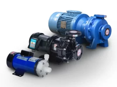
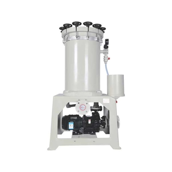
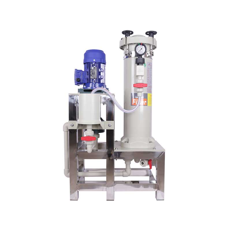
QEEHUA supplies magnetic pumps, vertical pumps, plastic centrifugal pumps, metering pumps, diaphragm pumps, and chemical filters for PCB, electroplating, wastewater, and surface-treatment systems. For PCB wet-process circulation, the common QEEHUA discussion is not only “which pump series.” It is “which duty point and material set are safe for this bath, this tank level, and this filter condition.”
For clean chemical circulation and many PCB wet-process baths, a plastic magnetic pump may fit when leakage reduction and corrosion resistance are the main concerns. For filtration loops, QEEHUA chemical filters can be checked together with pump flow, filter area, cartridge precision, and pressure rise. For tank-mounted or sump duties, vertical pump selection should also include submergence and low-level protection.
If your line has unstable spray pressure, fast filter plugging, uneven etching, or repeated cavitation, compare the calculated flow to the real installed system. The related QEEHUA article on PCB wet process filtration can help define the filter side, while the article on level, flow, pressure, and VFD interlocks can help prevent dry running, blocked-filter operation, and unsafe restarts.
Need help checking a PCB pump duty point? Send QEEHUA the bath name, working volume, nozzle count, target flow, TDH, filter pressure range, and current pump model. Email QEEHUA at info@qeehua.com for a practical selection review.
FAQ
How do I calculate pump flow for a PCB chemical tank?
Divide the working tank volume by the required turnover time, then compare that result with spray nozzle demand or filter-loop demand. The largest real process demand usually controls the pump flow target.
Should I size a PCB spray pump by pressure or by flow?
Use both. Select nozzle flow from the nozzle chart at the required pressure, multiply by active nozzle count, then check the pump curve at the head needed to hold pressure at the farthest nozzle.
Why does filter pressure change the required pump flow?
As cartridges load, pressure drop rises and the system curve becomes steeper. If the pump has no margin, the operating point moves to lower flow before the filter reaches the planned changeout condition.
Can I choose a larger pump to fix low flow in a PCB line?
Not automatically. First check suction pipe diameter, air pockets, nozzle balance, filter loading, valve position, and chemical viscosity. Oversizing can cause noise, water hammer, uneven spray, or operation away from the preferred curve range.
What data should I send QEEHUA for PCB pump flow selection?
Send bath chemistry, temperature, working volume, target turnover time, nozzle count and pressure, filter micron rating, clean and dirty pressure drop, pipe size, vertical lift, and current pump model if replacing an existing unit.
Sources
Technical references used: Hydraulic Institute Data Tool on pump and system curves; Lechler PCB cleaning and circuit-board nozzle applications; ZESTRON pressure and flow-rate discussion for PCB cleaning systems.
Final Selection Note
PCB wet-process pump flow is a process calculation before it is a pump-model choice. Calculate the required loop flow, add the real head and dirty-filter condition, verify the pump curve, and then confirm materials and protection logic. That sequence gives engineers a clearer RFQ and gives suppliers enough data to avoid a weak or oversized selection.