


PCB pump interlock logic should stop a chemical pump before low level, blocked flow, high pressure, or wrong valve position turns into dry running, filter rupture, leakage, or unstable wet-process quality. A good protection scheme does not depend on one alarm only. It uses liquid level, flow, pressure, motor load, and operator confirmation as layers.
This topic is different from normal pump sizing. A pump may be correctly selected, but the line can still fail if the control logic allows it to run against an empty tank, a blocked filter, a closed valve, or an unvented housing. The earlier QEEHUA article on PCB wet process pump dry running explains the low-level failure mode. This article focuses on the control design that prevents it.
Why PCB Pump Interlocks Matter
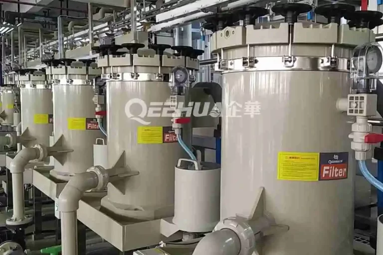
PCB wet process lines use pumps around acids, alkalis, etchants, developers, strippers, plating solutions, cleaning water, and filtration loops. A pump fault can become a process fault quickly. Low circulation may leave residual copper or residual film. High pressure can damage a cartridge filter. Wrong startup order can create water hammer. Unexpected restart during maintenance can expose workers to chemical, electrical, hydraulic, or mechanical energy.
OSHA’s Control of Hazardous Energy overview notes that electrical, mechanical, hydraulic, pneumatic, chemical, and thermal energy can all create worker risk during servicing. For PCB pump systems, that means automatic interlocks and maintenance lockout procedures should work together. A PLC stop signal is not a substitute for safe isolation before maintenance.


The Four Signal Layers to Protect
A useful pump protection design starts by separating four signals. Each signal catches a different failure mode. Relying on one pressure switch or one liquid level float leaves gaps.
Level is usually the first protection layer. In QEEHUA local pain-point records, missing low-level interlock can let a bath run down until the pump operates without enough liquid. This can damage seals, bearings, or isolation components. In a vertical pump, low level can also expose the suction zone and draw air into the loop.
Flow is the second layer. A motor may run while the line has no useful circulation. This can happen after gas binding, blocked suction, reversed valve direction, or severe filter clogging. If flow is not measured, operators may only notice the problem after the bath condition drifts.
A Practical Interlock Matrix
The table below is a starting logic matrix for PCB wet process circulation, filtration, and spray loops. Setpoints must match the actual bath, pump curve, filter housing, pipe layout, and plant standard. The purpose is to show how each alarm should lead to a defined action.
| Condition | Signal to monitor | Recommended action | Why it matters |
|---|---|---|---|
| Tank level low | Low-low level switch or level transmitter | Stop pump, block restart, trigger audible and visual alarm | Prevents dry running, air intake, heat damage, and chemical leakage. |
| No flow after start | Flow switch, flow meter, or differential pressure logic | Allow a short proving delay, then stop pump if flow is not confirmed | Finds closed valves, gas binding, blocked suction, or failed priming. |
| Filter pressure high | Inlet/outlet pressure or differential pressure | Alarm at warning level, stop at high-high level | Prevents cartridge rupture, bypass, housing stress, and particle return. |
| Outlet valve closed | Valve position feedback or pressure rise pattern | Do not start pump, or trip after abnormal pressure rise | Reduces deadheading, overheating, and sudden water hammer. |
| VFD speed too low | Speed reference and feedback | Hold above minimum stable speed or switch to duty standby pump | Low speed may not maintain spray exchange or filter turnover. |
| Maintenance mode active | Local selector, LOTO procedure, permit status | Disable automatic restart and require manual confirmation | Protects workers during inspection, filter change, and pump service. |
Pressure logic needs context. High pressure with low flow points to blockage. Low pressure with low flow points to suction starvation, loss of prime, or a worn pump. QEEHUA’s guide to electroplating filter pressure that is too high covers the pressure-side failure path in more detail.

How VFD logic should be used
A VFD can soften startup, tune flow, and reduce valve-throttling losses. It is not a cure for a bad suction layout or a blocked filter. The pump affinity laws show why changing speed changes flow, head, and power. That is useful for control, but it also means the minimum speed must still meet the process flow requirement.
For PCB spray, etching, and plating loops, do not let the VFD run the pump below the minimum speed that maintains bath exchange. If the process needs a fixed turnover rate, use flow feedback or a verified speed-to-flow curve. If the VFD reports overload, phase loss, or repeated trips, stop and inspect the pump and line instead of increasing the speed command.
Startup, Shutdown, and Maintenance Logic
Good interlock design also defines sequence. QEEHUA local maintenance notes use a simple startup rule: open inlet, vent air, then open outlet. For shutdown, stop the pump first, then close valves according to the plant procedure. This avoids starting against a closed or air-locked line.
For automatic systems, the PLC should check permissives before start. Minimum permissives include adequate liquid level, inlet valve open, outlet path available, emergency stop healthy, drive ready, and no active leak alarm. After start, the logic should prove flow within a short delay. If flow does not appear, the system should stop and alarm.
Maintenance needs a separate mode. The Canadian Centre for Occupational Health and Safety describes hazardous energy control programs as a way to identify and control energy sources before work begins. In a chemical pump area, this includes electrical power, pressurized liquid, trapped chemical, rotating parts, and stored pressure inside filters.
Interlock logic can prevent many automatic faults. It cannot replace drain, depressurize, lockout, tagout, and verification before service. This is especially important when teams change filters, clean crystallized lines, replace seals, or inspect a pump after a trip.

How to Specify the Pump and Protection Package
For a new PCB line or retrofit, send the pump supplier more than flow and head. Provide chemical name, temperature, specific gravity, solids risk, tank level range, pipe layout, filter type, expected pressure, motor voltage, control mode, and alarm philosophy. This lets the supplier check both pump selection and protection needs.
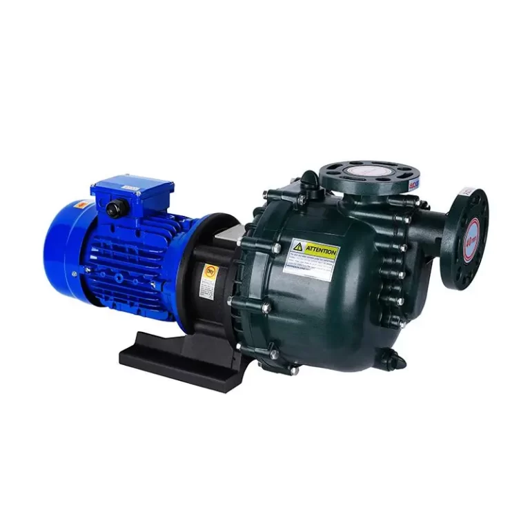
If leakage control is important, review QEEHUA’s magnetic pump products. If the real issue is repeated shock, read the QEEHUA article on PCB wet process water hammer.
If suction instability keeps triggering flow alarms, compare the interlock design with the article on NPSH margin for PCB chemical pumps. This separates suction protection from discharge-side pressure and shock protection.
A strong specification does not only ask for a pump model. It asks for the safe operating envelope, minimum continuous flow, dry-run protection method, pressure alarm limits, VFD speed range, and restart rule after a trip.
FAQ
What interlocks should a PCB chemical pump have?
A PCB chemical pump should normally have low-level shutdown, flow confirmation, pressure or differential pressure alarm, motor overload protection, valve permissives, and manual reset after a trip.
Is a level switch enough for dry-run protection?
A level switch is a strong first layer, but it may not catch blocked suction, air pockets, failed priming, or wrong valve position. Use flow or pressure confirmation as a second layer.
Should a pump restart automatically after a low-flow alarm?
Automatic restart is risky after a low-flow alarm. The operator should confirm liquid level, suction condition, valve position, filter pressure, and leakage before resetting the pump.
Can VFD control replace flow and pressure switches?
No. A VFD controls speed, but it does not prove that liquid is moving through the process. Flow and pressure feedback are still needed for blocked filters, closed valves, or suction failure.
What should OEMs include in a pump protection RFQ?
OEMs should include chemical, temperature, tank level range, target flow, filter pressure, pipe layout, voltage, control mode, alarm setpoints, VFD requirement, and restart philosophy.